Method Statement for General Pre-casting Works at Pre-casting Yard
1. INTRODUCTION
1.1 PURPOSE OF THE DOCUMENT
The purpose of this procedure is to outline General Arrangements, Construction Methodologies and other works all in accordance with the contract specification and details shown on the drawing, related to the pre-casting of segments composing the viaduct superstructure works of the HCMC Metro Project.
Where it is identified that there is a need to change the method of work due to unforeseen circumstances, then revision, authorisation and issue will follow the same procedure as the original.
1.2 PROJECT DESCRIPTION
Ho Chi Minh City Urban Railway Construction Project – Ben Thanh – Suoi Tien section (Line 1), contract Package 2 consists of approximately 12 km long of elevated viaduct structures, erected by span-by-span Method.
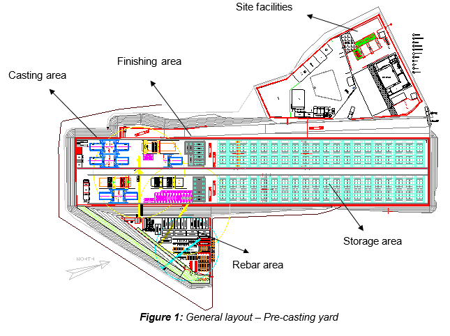
All activities related to the construction of reinforced concrete precast segments will be carried out in the precast yard, located in Road 11, Long Binh Ward, District 9 (HCMC), covering approximately 40,000 square metres of area, including:
- Rebar storage & rebar jigs area (rebar cage fabrication area)
- Segment casting area (moulds)
- Stores & workshop area
- Segment storage area
- Site offices & basic facilities for staffs
1.3 SCOPE OF WORK
This procedure is developed for application in the scope of works and applies to the casting Operations of the Precast segments composing the viaduct superstructure works of the HCMC Metro Project.
1.4 REFERENCES
This procedure is formed by the following method statements:
| Description | Document Ref. |
|---|---|
| General precasting works at precasting yard | HCMC-261-CSYD-CWS-MST-00012 |
| Rebar Cut & Bend works | HCMC-261-CSYD-CWS-MST-00013 |
| Rebar cage assembly | HCMC-261-CSYD-CWS-MST-00014 |
| Precast segment production – Long Line Typical mould | HCMC-261-CSYD-CWS-MST-00015 |
| Geometry control for short line casting method | HCMC-261-CSYD-CWS-MST-00016 |
| Casting sequence - Short Line Typical segments | HCMC-261-CSYD-CWS-MST-00017 |
| Casting sequence - Short Line Pier segments | HCMC-261-CSYD-CWS-MST-00018 |
| Casting sequence - Long Line Typical segments | HCMC-261-CSYD-CWS-MST-00019 |
| Segment concreting works | HCMC-261-CSYD-CWS-MST-00020 |
| Curing of segments | HCMC-261-CSYD-CWS-MST-00021 |
| Segment marking | HCMC-261-CSYD-CWS-MST-00022 |
| Segment Lifting & Handling Works | HCMC-261-CSYD-CWS-MST-00023 |
| Segment Finishing works | HCMC-261-CSYD-CWS-MST-00024 |
| Segment remedial works | HCMC-261-CSYD-CWS-MST-00025 |
| Segment storage & ½ stacking | HCMC-261-CSYD-CWS-MST-00026 |
| Segment Delivery & Transportation | HCMC-261-CSYD-CWS-MST-00027 |
| PT duct fabrication | HCMC-261-CSYD-CWS-MST-00028 |
| Precast segment production – Short Line Pier mould | HCMC-261-CSYD-CWS-MST-00040 |
| Precast segment production – Short Line Typical mould | HCMC-261-CSYD-CWS-MST-00041 |
| Geometry control for long line casting method | HCMC-261-CSYD-CWS-MST-00042 |
All reference documents are intended to refer to the last issued revision.
1.5 DEFINITIONS
- Method Statement
A work instruction detailing technical/engineering methodology for a particular activity including the Hazard Analysis & Risk Assessment.
- HRA (Hazard & Risk Assessment)
Identify all hazard & risk per activity, and reduce the probably of each risk by using different kind of solutions, such as: training for workers to prevent and inform them, inspection, check-list etc…
- ITP (Inspection & Test Plan)
The purpose of this procedure is to clearly identify all inspection, check-list and test which have to be done in order to respect with Quality & Safety requirements.
- Precasting yard (PCY)
Area used to manufacture and temporary store all precast segments.
- U-Section
Precast concrete section typically, U-shaped, consisting of a bottom slab, two side webs and lateral top flanges. It concerns all segment used for this project.
- Typical segment
The segments used in the central parts of the spans and between the pier segments. They are characterized by an almost constant shape.
- Pier segment
It defines the first and the last segment of the span, and which are positioned on a pier by means of bearings.
- Fresh cast segment (F/C)
The segment being cast in the formwork (also called mould). One face is formed using a fixed bulkhead; the other face is formed using either a Stop-End or the match-cast (M/C) segment face.
- Match-cast segment (M/C)
Match-casting means the segment is cast in the formwork between either a Stop-End or a fixed bulkhead formwork at one end, and a previously fresh cast segment (F/C) at the other end. Match-casting is accomplished by either the Short Line or Long Line casting method.
- Short line casting method
Casting segments one at a time in the mould between a fixed bulkhead at one end and a previously fresh cast segment at the other. The first segment is cast between a fixed bulkhead and a movable bulkhead, called Stop-End.
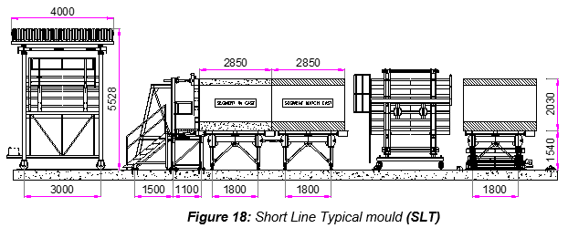
- Short Line Typical mould (SLT)
Mould which is used to cast typical segment of curved and straight spans, by using the Short line casting method. For this project, 3 Short Line Typical moulds (SLT#1, SLT#2 & SLT#3) are provided.
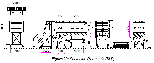
- Short Line Pier mould (SLP)
Mould which is used to cast pier segment of straight and curved spans, by using the Short line casting method. For this project, 4 Short Line Pier moulds (SLP#1, SLP#2, SLP#3 & SLP#4) are provided.
- Long line casting method
Casting segments on a mould of sufficient length to permit the cumulative casting of segments for the entire length of a span. With this method, the first segment is cast between two Stop-End and successive segments are cast between a Stop-End on one end and the previously fresh-cast segment on the other.
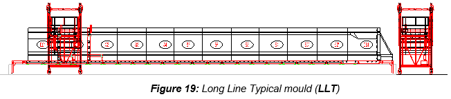
- Long Line Typical mould (LLT)
Mould which is used to cast typical segments of straight spans, by using the Long line casting method. For this project, 3 Long Line Typical moulds (LLT#1, LLT#2 & LLT#3) are provided.
- Span
As span is consisted of 2 pier segments and several typical segments. Each pier segment is located at both end. The U section varies from 11 to 37m span length.
- Curved span
As span which horizontal alignment is not straight. Minimum radius of curved span for this project is from 300m.
- Span by span Method
This method of construction is applicable when the span is built by beginning at one pier and proceeding towards the next pier. This type of construction needs special equipment called “Launching gantry” by means of which the whole span is hung until longitudinal final post-tensioning (PT) would be applied.
- Mould (casting equipment)
The steel structure formwork into which the fresh concrete is poured to cast a segment. Precasting bed
Area where is located short line and long line moulds.
- Soffit table
This element is the lower steel structure of the mould as base support of the segment used for Short line casting method. It is formed by the following elements:
The soffit table can be either used for Short Line Typical mould or Short Line Pier mould with some geometry adjustment, such as:
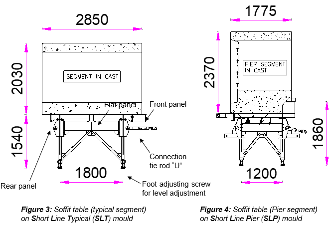
The soffit table is a movable steel structure which can be either moved with Tower crane / Gantry crane or manipulator if carrying the complete segment.
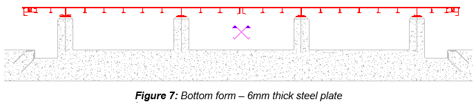
- Bottom form
This element is the fixed steel structure, and lower part of the mould as base support of the segment used for Long line casting method.
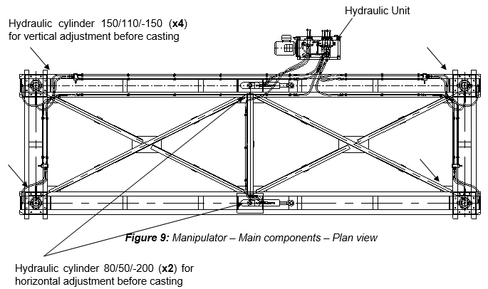
The manipulator is designed to work under the bottom forms, and its wheels run on the rail track positioned on the ground. The manipulator is a movable steel structure, by means of hydraulic cylinders, which enables the movement of completed segments to the following locations:
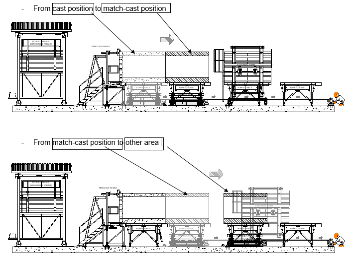
It is moved longitudinally on rails with wheels due to an electrical winch, and is provided only for SLT and SLP mould.
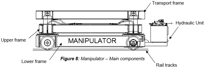
It is moved longitudinally on rails with wheels, and is provided only for SLT and SLP moulds. The manipulator upper frame can rotate on the lower one by means of 2 hydraulic jacks to adjust the position of the segment.
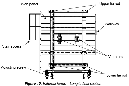
- External side forms
External side forms are the lateral closing steel panels of the mould, necessary for the casting of the web segment and top flange, connected by means of threaded bars upper & lower. This is a movable steel structure which moves longitudinally on pivoting wheels with 4 adjusting screws, provided for the vertical positioning of the side forms. The panels are equipped with pneumatic vibrator 2 for each side for typical segment, and only 1 per side for pier segment.
- Portal frame & Inner forms
Refers to a steel structure fitted with four wheels moving on rails. It supports the inner forms for the casting of the web and top flange. It allows lengthwise translation of the inner forms. Also, it provides a roof, covering the mould, from sun and water. The inner forms are designed to shape the inner part of the concrete segment. They are hinged to a portal frame running on the rail track.
The operations of opening-closing of the panels are made by hydraulic jacks mounted between the portal frame and the formwork. During the process of casting, the web & inner panels are held with the upper tie rod and telescopic lower props between the two opposite inner forms.
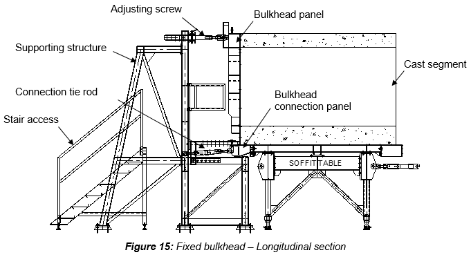
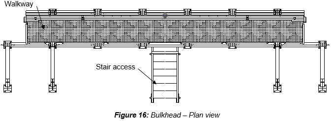
- Fixed bulkhead
The bulkhead is the fixed transverse closing panel of the mould. The bulkhead is welded on steel frame to create a very stiff body, including a working platform with stairs, walkway and removable parapets for the passage of the inner forms. The bulkhead is used for the short line moulds (SLT & SLP).
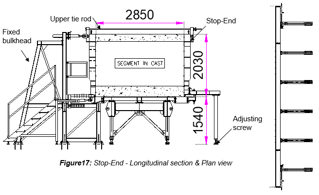
- Stop-End (S/E)
The Stop-end is the mobile bulkhead, used as transverse closing panel of the mould, shared between LLT mould (first segment of the span “S1”), and also for the SLT mould (middle segment of the span “S6”). For further details, refer to the following method Statements:
- Casting sequence for Short Line Typical segments HCMC-261-CSYD-CWS-MST-00017
- Casting sequence for Long Line Typical segments HCMC-261-CSYD-CWS-MST-00018
2. SAFETY & ENVIRONMENTAL RISKS
2.1 HAZARD ANALYSIS & RISK ASSESSMENT
Hazards Analysis and Risks assessment are carried out and attached in each Method Statement. This document will identify all the hazards to ensure adequate control measures and strategies are in place to mitigate as much as possible the risks.
All personnel carrying out the work will be properly trained by experienced supervision. Besides, all personnel shall wear the appropriate PPE (Personal Protective Equipment), such as Safety shoes, safety helmet and safety harness if required.
2.2 TOOLS AND EQUIPMENT
All tools & equipment shall be in safe condition before utilisation and fit for its purpose. Where applicable, before each shift, equipment shall be visually checked for the mechanical and structural soundness.
2.3 EMERGENCY RESPONSE
In the event of an accident/incident, response will carried out in the appropriate procedure, such as:
- Remedial Actions, proposing actions to ensure that the Accident/Incident will be fully fixed, as required, managed by the Responsible within a target date.
- Preventive Actions, proposing actions to ensure that the Accident/Incident will never happen again, including for example: Toolbox Meeting (TBM) held by the Safety Officer to ensure that Site Team (Workers, Supervisors & Engineers) fully understand methods & risks.
Prestart and Toolbox talk will reinforce safety requirements prior to commencement of the work.
3. CONSTRUCTION RESOURCES
In principle every type of work involves the following resources:
3.1 PERSONNEL
The personnel involved are such as:
- Precasting yard Manager
- Segment casting Superintendent
- Site engineers
- QA/QC Engineers
- Safety Officers
- Environmental engineer
- Supervisors
- Surveyors
- Plant Operators (Tower cranes & Gantry Cranes)
- Finishing workers
- Steel fixers
- Riggers
- Reinforcement workers
- Others workers
- Electricians
3.2 PLANT AND TOOLS
The following equipment shall be used for all precasting works:
| • Long Line precasting bed (typical set of mould) | |
|---|---|
| - Fixed bottom form (on concrete foundation) | Full length of span |
| - External side forms (left & right) | 2 Nos |
| - Inner forms (left & right) | 2 Nos |
| Portal frame for inner forms (including the roof) | 1 Nos |
| Stop-End #1 (always stay on long line precasting bed) | 1 Nos |
| Stop-End #2 (Stop-end used to cast the first segment “S1”) | 1 Nos |
| Hydraulic system (for inner forms) | 1 Set |
Each displayed quantities above belong for only 1 LLT mould. Each long line precasting bed has 2 Long Line Typical mould, so is able to cast 2 segments simultaneoulsy. 3 long line precasting beds are provided in the precasting yard.
| • Short Line precasting bed | |
|---|---|
| Soffit tables | 3 Nos |
| Manipulator with 4 hydraulic vertical & horizontal jacks | 1 Nos |
| External side forms (left & right) | 1 Set |
| Inner forms (left & right) | 1 Set |
| Portal frame for inner forms (including the roof) | 1 Set |
| Fixed bulkhead (with supports, Stairs & platforms) | 1 Nos |
| Stop-End #2 (Stop-End used to cast the first segment “S6”) | 3 Nos for 9 formworks |
| Hydraulic system (for inner form) | 1 Set |
The short line precasting bed can be divided in 2 types: Short Line Typical mould for Typical segments – 3 Nos, and Short Line Pier (SLP) mould for Pier segments – 4 Nos.
Lifting equipment
- Tower Crane TC#1 (6.89 ton–50m): Dedicated to mould operations & others activities if needed.
- Tower Crane TC#2 (6.89ton–50m): Fully dedicated to rebar cage assembly works
- (Cut & Bend steel rebars supply), and lifting rebar cage from rebar jig area to rebar cage storage.
- Tower Crane TC#3 (4.3Ton – 35m): Fully dedicated to unloading standard length of rebar, storage of rebar, and Cut & Bend works.
- Gantry crane GC#1 – 10Ton – Span 1 (31.5m) – Lifting for mould preparation & rebar cages
- Gantry crane GC#2 – 50Ton – Span 1 (31.5m) – Lifting for storage or relocation segments (42ton)
- Gantry crane GC#3 – 50Ton – Span 2 (31.5m) – Lifting for storage or relocation segments (42ton)
Concrete equipment
- Concrete trucks (provided by Sumitomo Corporation).
- Concrete pumps (Expected radius required = 36m)
Others
- Trailers (for segment delivery)
- Lifting frame for rebar cages
- Lifting frame for segment (also called “spreader beam”)
- Cutting & Bending Machines
- Jigs for assembling reinforcing steel
- Concrete bucket
- Air compressor (for mould cleaning and external form vibration operations)
- External form vibrator (fixed in position within the mould soffit and side-forms)
- Setting out instruments (Total station, auto-level, etc.)
- Concreting equipments (frequency converters, concrete vibrators, back up vibrators)
- Electric tools
- Hand tools (trowel, wheel barrow, chute, rubber mallet, etc.)
- Chains / slings / shackles
- Safety signs
- Generator set
- Water & fuel tanks
Gantry cranes run on railways positioned on appropriately designed foundations (designated as East and West spans). Each span is 31.5m.
One Gantry Crane 10ton will be used for the West Span. This position allows flexibility to the Tower Crane TC #1 operations, regarding mould preparation works and rebar cages lifting.
The two gantry crane 50ton, located on each span, will carry out all handling segment works (transfer to mould, finishing area, storage ½ stacking or loading area with trailers).
For more details and general arrangements of the precast Yard, location of plant, tools and common areas, refer to Appendix B.
3.3 MATERIALS
- Concrete
- Reinforcement steel rebar
- Demoulding oil
- Curing compound
- Debonding agent
- Concrete spacers
- Lifting holes former (for typical segment, 4 holes for purpose of fixing thru prestress bar for the lifting of the segments). The holes shall be formed used corrugated duct.
- Post-tensioning elements (ducts, anchor, bearing plates, etc.)
- Lubricants
- Sand, water, woods, steel, etc.
4. CONSTRUCTION PROCESS
4.1 PRELIMINARY
The bridge is built by assembling the segments of variable longitudinal lengths and during the construction 3 types of segments are used:
- Typical segments of curved span, by means of the Short Line Typical mould (SLT).
- Typical segments of straight span, by means of the Long Line Typical mould (LLT).
Pier segments of straight & curved spans, by means of the Short Line Pier mould (SLP).
TYPICAL SEGMENTS OF CURVED SPANS
- TYPICAL SEGMENTS OF STRAIGHT SPANS
- PIER SEGMENTS OF STRAIGHT & CURVED SPANS
4.2 CONSTRUCTION CYCLE
The main activities for segment precast production include the following steps:
- Rebar cage is store next to casting location completed and equiped with corrugated PT duct and spacer blocks
- Cleaning & applying of mould release agent
- Placement of pre-checked rebar cage in the mould
- Apply debonding agent to Match-Cast (M/C) segment joint surface
- Place and position the M/C segment or Stop-End S/E (if 1st segment)
- Close external forms against Stop-End #1 (or fixed bulkhead) and M/C segment (or Stop-End #2)
- Installation of inserts (CP3, temporary PT…)
- SCC/GS inspection prior to inner forms closure
- Close and adjust inner forms against S/E #1 (or fixed bulkhead) & M/C segment (or S/E #2)
- Final inspection & geometry control before casting
- Install and position inflatable tubes (called also “satujo”)
- Cast segment
- Curing of the Fresh Cast (F/C) segment
- Strip formworks after stripping concrete strength reached, and survey of as-built geometry done
- Marking of segment (ID number & date of casting)
- Bond breaking between F/C segment and M/C segment
- Relocate F/C segment to M/C position
- Transfer cured segment to finishing area, after lifting strenght required reached
- Segment finishing works
- Remedial works for segment (if needed)
- Storage of segment
- Load segment on trailers for site delivery
5.1 METHODOLOGY
Basically, the construction methodology consists of:
5.1 ASSIGNMENT, SAFETY INDUCTION & COMPETENCY OF PERSONNEL
All site personnel shall attend a Health & Safety Environment (HSE) induction training session. Induction will be provided by the Safety Officer to ensure they are fully awarded and understand all Safety requirements. Site engineers & Supervisors shall ensure that the work is carried out by duly certified and adequately trained workers.
5.2 HAZARD ANALYSIS & RISK ASSESSMENT
Hazard Analysis & Risk Assessment will be regularly reviewed by both production and HSE Department to ensure that all the hazards have been identified and adequate control measures are in place.
5.3 PLANT & EQUIPMENT CHECKS COMPLETED
At the beginning of each shift, all equipment shall be visually inspected for mechanical & structural soundness. Damaged plant and equipment shall not be used and will be tagged out of service until repaired to manufacturer’s requirements or may be removed from site.
5.4 REBAR CUT & BEND WORKS
Procedures related to rebar cut and bend works shall refer to this detailed Method Statement in Document reference: HCMC-261-CSYD-CWS-MST-00013
5.5 REBAR CAGE ASSEMBLY
Procedures related to rebar cages assembly shall refer to this detailed Method Statement in Document reference: HCMC-261-CSYD-CWS-MST-00014
5.6 PRECAST SEGMENT PRODUCTION – SHORT LINE TYPICAL MOULD
Procedures related to Mould preparation and operations for SLT shall refer to this detailed Method Statement in Document reference: HCMC-261-CSYD-CWS-MST-00041
5.7 GEOMETRY CONTROL FOR SHORT LINE CASTING METHOD
Procedures related to geometry controls and survey works for the short line casting method shall refer to this detailed Method Statement in Document reference: HCMC-261-CSYD-CWS-MST-00016
5.8 CASTING SEQUENCE
Procedures related to Casting sequence for Short Line Typical segment shall refer to this detailed Method Statement in Document reference: HCMC-261-CSYD-CWS-MST-00017
Procedures related to Casting sequence for Short Line Pier segment shall refer to this detailed Method Statement in Document reference: HCMC-261-CSYD-CWS-MST-00018
Procedures related to Casting sequence for Long Line Typical segment shall refer to this detailed Method Statement in Document reference: HCMC-261-CSYD-CWS-MST-00019
5.9 SEGMENT CONCRETING WORKS
Procedures related to concreting works shall refer to this detailed Method Statement in Document reference: HCMC-261-CSYD-CWS-MST-00020
5.10 CURING OF SEGMENTS
Procedures related to curing works shall refer to this detailed Method Statement in Document reference: HCMC-261-CSYD-CWS-MST-00021
5.11 SEGMENT MARKING
Procedures related to segment marking works shall refer to this detailed Method Statement in Document reference: HCMC-261-CSYD-CWS-MST-00022
5.12 SEGMENT LIFTING & HANDLING WORKS
Procedures related to segment lifting and handling works shall refer to this detailed Method Statement in Document reference: HCMC-261-CSYD-CWS-MST-00023
5.13 SEGMENT FINISHING WORKS
Procedures related to segment finishing works shall refer to this detailed Method Statement in Document reference: HCMC-261-CSYD-CWS-MST-00024
5.14 SEGMENT REMEDIAL WORKS
Procedures related to remedial works for segments shall refer to this detailed Method Statement in Document reference: HCMC-261-CSYD-CWS-MST-00025
5.15 SEGMENT STORAGE & ½ STACKING
Procedures related to the storage and ½ stacking shall refer to this detailed Method Statement in Document reference: HCMC-261-CSYD-CWS-MST-00026
5.16 SEGMENT DELIVERY & TRANSPORTATION
Procedures related to segment delivery and transportation shall refer to this detailed Method Statement in Document reference: HCMC-261-CSYD-CWS-MST-00027
5.17 PT DUCT FABRICATION
Procedures related to Post Tensioning duct fabrication shall refer to this detailed Method Statement in Document reference: HCMC-261-CSYD-CWS-MST-00028
5.18 PRECAST SEGMENT PRODUCTION – SHORT LINE PIER MOULD
Procedures related to Mould preparation and operations for SLP shall refer to this detailed Method Statement in Document reference: HCMC-261-CSYD-CWS-MST-00040
5.19 PRECAST SEGMENT PRODUCTION – LONG LINE TYPICAL MOULD
Procedures related to Mould preparation and operations for LLT shall refer to this detailed Method Statement in Document reference: HCMC-261-CSYD-CWS-MST-00015
5.20 GEOMETRY CONTROL FOR LONG LINE CASTING METHOD
Procedures related to geometry controls and survey works for the long line casting method shall refer to this detailed Method Statement in Document reference: HCMC-261-CSYD-CWS-MST-00042
6. ACTIVITY HOLD POINTS
Hold points will be identified in the Inspection and Test Plan (ITP)
7. INSPECTION & RECORDS
All Inspection / check-lists & documents records will be identified in the Inspection and Test Plan (ITP).