Method Statement for Segment Storage & Stacking
1. INTRODUCTION
1.1 PURPOSE OF THE DOCUMENT
The purpose of this document is to describe the procedure of operation to be followed for the storage of concrete precast segments, and ensure that all works will be conducted safely in accordance with the technical drawings, and the project specifications.
1.2 PROJECT DESCRIPTION
Ho Chi Minh City Urban Railway Construction Project – Ben Thanh – Suoi Tien section (Line 1), contract Package 2 consists of approximately 12 km long of elevated viaduct structures, erected by span-by-span Method.
1.3 SCOPE OF WORK
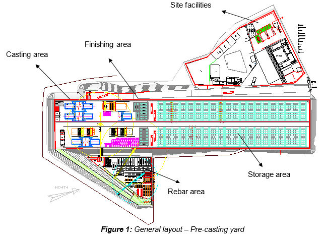
This method statement outline the principle of the storage of all precast concrete segments in the storage area of the precasting yard, composing the viaducts of HCMC Line 1 – Metro Project.
1.4 REFERENCES
- Specifications:
- Reference is made to clause 12.4.2 “Precast segment handling, storage and transport” from Outline Construction Specification Package 2: Civil (Elevated & Depot).
- Method Statement:
- Method Statement “Segment lifting & handling works” – HCMC-261-CSYD-CWS-MST-00023
- Method Statement “Segment delivery & transportation” – HCMC-261-CSYD-CWS-MST-00027
- Drawing:
- Technical drawing “Precasting yard - Segment storage facilities” – FVR-TEC-DWG-3140-003
All reference documents are intended to refer to the latest issued revision.
1.5 DEFINITIONS
In this Terms & conditions the meanings assigned to words and expressions shall be the following: - “PCY” means Precasting yard - “Segment lifting frame” or “Spreader beam” means the frame that is required for the lifting and transporting of the complete segment from the mould either to the finishing area or storage area. This equipment shall be designed so that there is no permanent distortion of the segment either during lifting, transport or placing on trailer prior to deliver on site. - “Simple layer storage” means that segments are stored side by side without stacking - “Stacking” means the placing of 2 segments above and inside 3 Nos 1st layer of segments which are supported on concrete support blocks.
Further definitions have been given in Section 1.5 “Definitions” of the Method Statement “General precasting works at precasting yard” HCMC-261-CSYD-CWS-MST-00023.
2. SAFETY & ENVIRONMENTAL RISKS
2.1 HAZARD ANALYSIS & RISK ASSESSMENT
Hazards Analysis and Risks assessment are carried out and attached in each Method Statement. This document will identify all the hazards to ensure adequate control measures and strategies are in place to mitigate as much as possible the risks.
All personnel carrying out the work will be properly trained by experienced supervision. Besides, all personnel shall wear the appropriate PPE (Personal Protective Equipment), such as safety shoes, safety helmet, reflective vest and safety harness if required.
2.2 TOOLS AND EQUIPMENT
All tools & equipment shall be in safe condition before utilisation and fit for its purpose.
2.3 EMERGENCY RESPONSE
In the event of an accident/incident, response will be carried out in the appropriate procedure, such as: - Remedial Actions, proposing actions to ensure that the Accident/Incident will be fully fixed, as required, managed by the responsible within a target date. - Preventive Actions, proposing actions to ensure that the Accident/Incident will never happen again, including for example: Toolbox Meeting (TBM) held by the Safety Officer to ensure that Site Team (Workers, Supervisors & Engineers) fully understand methods & risks.
3. CONSTRUCTION RESOURCES
3.1 PERSONNEL
The personnel involved are such as: - PCY supervisor - Storage supervisor - Gantry crane Operators (50 tons) - Riggers - Workers
3.2 PLANT AND TOOLS
The following equipment shall be used: - 50 Ton gantry cranes - Spreader beam - Chains / slings / shackles - Hand tools
3.3 MATERIALS
- Segment support blocks (Type A & B)
- Timber or plywood
- Sand bag
4. CONSTRUCTION PROCESS
4.1 PRELIMINARY
Once the segment (maximum weight 42 Ton) is ready for lifting (refer to the method statement “Segment lifting & handling works” HCMC-261-CSYD-CWS-MST-00023) and all finishing works have been completed with that particular segment, it shall be transferred to the storage area.
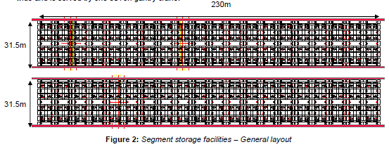
The storage area is composed of two storage lines. Each line is approximately 230m long and 31.5m wide and is served by one 50Ton gantry crane.
Each segment shall be stored together with the other segments of a same span in a designated area that has been identified by the storage supervisor. The arrangements for storage of the segments shall facilitate later removal of the segments in the sequence of erection, without the need for any rearrangement in the stacking area. It shall start from the finishing area to the end of the storage area.
4.2 PRINCIPLE OF STORAGE
Capacity of the storage area with only one layer shall be 360 segments, while the capacity of the storage area with stacking method shall be 520 segments as explained below:
- 1st layer of segment storage
On each storage line (31.5m), 9 segments can be stored longitudinally on a same row respecting a minimum side spacing, varying from 400 to 1145mm, and a front and rear spacing of 300mm as follows:
The 4 first cast segments shall be stored on the 1st layer, at alternate position where they will carry the load from 2nd layer of segment storage.
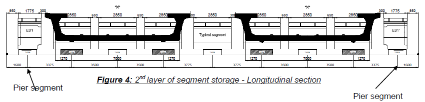
- 2nd layer of segment storage
Two segments shall be stacked on top of 2 Nos of 1st layer segments, following the principle: - Stacked 2nd layer segments will be stored transversally - Pier segments of the span will be stored as 1st layer storage, without any segment stacked on it.
4.3 SEGMENT SUPPORT BLOCKS
All precast segments shall be firmly supported for storage on three point bearing system under. The ground or space between the segment support blocks shall be cleared and levelled so as to prevent the segment being supported other than on the support blocks.
- 1st layer of segment storage
Each 1st layer of segment storage will be supported by three concrete support blocks set on the ground such as:
- Type A: used for segments carrying the load from 2nd layer of segment storage
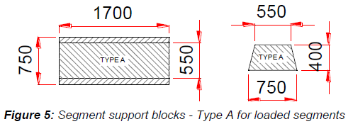
- Type B: used for segments stacked in single layer or not carrying any 2nd layer segment
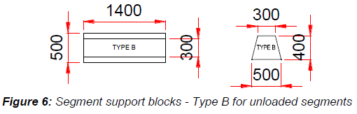
For both type of support blocks, timber shall be used as temporary bearings between concrete block and segment, in order to prevent damage to segment. - 2nd layer of segment storage
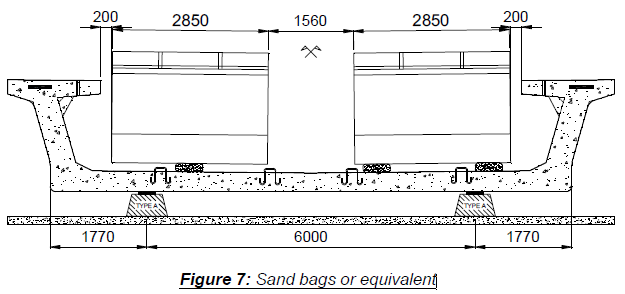
For 2nd layer of segment storage, the three point bearing shall be made of sand bags which the size is 500 long x 300 width x 150 high (mm). Those 3 point supports shall allow the segment to distribute its load without causing any twist to the segment carrying the load.
4.4 SEGMENT TRANSPORTATION TO ERECTION SITE
Handling of segment must be done carefully.
Segments will be removed from the storage area to be transported to erection sites, when required by the erection schedule. Before leaving the storage area, each segment shall be inspected.
For more details, refer to the method statement “Segment delivery & transportation” HCMC-261-CSYD-CWS-MST-00027
5. ACTIVITY HOLD POINTS
Hold points will be identified in the Inspection & Test Plan. Refer to the ITP “Precast segment production”
6. INSPECTION & RECORDS
All Inspection / check-lists & documents records will be identified in the Inspection & test Plan. Refer to the ITP “Precast segment production”