Method Statement for Casting Sequence - Long Line Typical Segment
1. INTRODUCTION
1.1 PURPOSE OF THE DOCUMENT
The purpose of this procedure is to describe the sequence of operation to be followed to precast typical segments of the typical straight spans, representing the major part of the HCMC Metro Project, and ensure that all works will be conducted safely in accordance with the drawings and the project specifications.
1.2 PROJECT DESCRIPTION
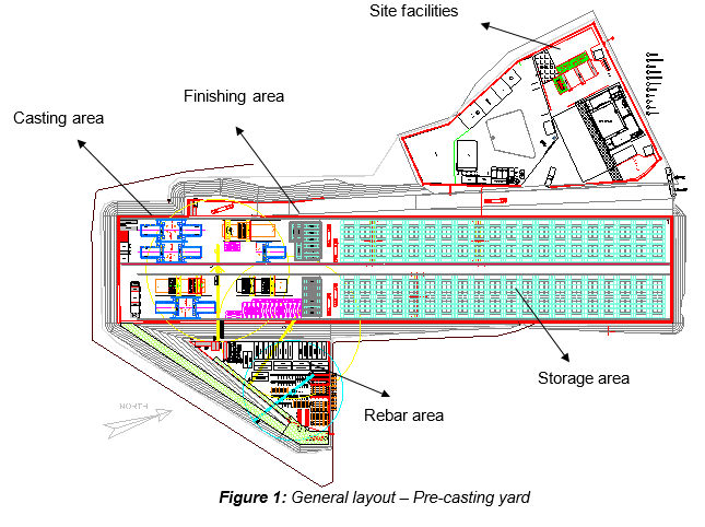
Ho Chi Minh City Urban Railway Construction Project – Ben Thanh – Suoi Tien section (Line 1), contract Package 2 consists of approximately 12 km long of elevated viaduct structures, erected by span-by-span Method. All activities related to the construction of reinforced concrete precast segments will be carried out in the precast yard, located in Road 11, Long Binh Ward, District 9 (HCMC), as per layout in figure 1.
1.3 SCOPE OF WORK
This procedure is developed for clarifying the casting sequence of typical segments produced with the Long Line Method.
1.4 REFERENCES
Reference is made to Clause 12.4.1 “Precast Segment Casting”, section 12-13 of 19, from Outline Construction Specifications Package 2: Civil (Elevated & Depot).
1.5 DEFINITIONS
All relevant definitions have been given in Section 1.5 “Definitions” of the General Method Statement refer to:
- HCMC-261-CSYD-CWS-MST-00012 “Precasting works”
2. SAFETY & ENVIRONMENTAL RISKS
Being this procedure a simple description of the casting sequence used to cast typical segment (Straight span) with the Long Line Method, no specific hazards have been analysed and attach to the present Method Statement.
All the risk assessments concerning the operations described in this procedure, such as: concrete pouring, segment lifting, etc. will be carried out in the appropriate document.
3. CONSTRUCTION RESOURCES
Being this procedure a simple description of the casting sequence used to cast typical segment, requirement of personnel, equipment & tools and materials is not required to be mentioned specifically in this Method Statement.
4. LONG LINE TYPICAL
4.1 DESCRIPTION
Listing of long line for the production of typical segments:
- Long Line Typical #1 (LLT #1)
- Long Line Typical #2 (LLT #2)
- Long Line Typical #3 (LLT #3)
Each Long Line is able to cast 2 segments simultaneously.
4.2 COMPONENTS
Listing of equipment for the production of typical segment with Long Line method:
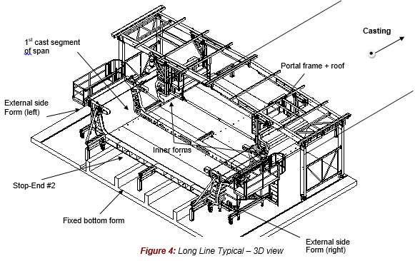
| 1. Fixed bottom form (on concrete foundation) | Full length of line |
| 2. External side forms (left & right) | 2 Sets |
| 3. Inner form (left & right) | 2 Sets |
| 4. Portal frame for inner forms (including the roof) | 1 Set |
| 5. Stop-End #1 (common Stop-End) | 1 Nos |
| 6. Stop-End #2 (Stop-End use to cast 1st segment of the span) | 3 Nos for 9 formwork |
| 7. Hydraulic system (for inner form) | 1 Set |
Note that all these quantities have to be multiple by 2, due to each Long Line is able to cast two segments simultaneously.
5. CONSTRUCTION SEQUENCE
5.1 INTRODUCTION
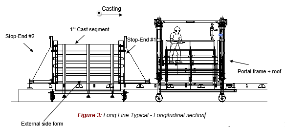
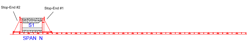
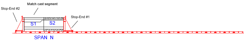
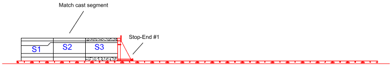
Segments are match-cast progressively on the Long Line formwork by step-by-step advancement of movable formwork units and a movable bulkhead, called Stop-End. The soffit form of the Long Line system is fixed as a long casting bed and only the internal & external side forms & Stop-End are moved following the respective position of each segment to be cast.
Each Long Line precasting bed is equipped with 2 moulds (each of them holding a front Stop-End #1) and one backward Stop-End #2, which is always and only used to cast the first field segment of each straight span.
5.2 TYPICAL CYCLE OF MOULD OPERATION
- Stripping of external & internal moulds & moved for next segment casting.
- Cleaning & preparation of form including application of form oil.
- Setting up & aligning of soffit formwork with survey
- Closing of external formwork (left & right)
- Placing of rebar cage
- Final fixation of PT Duct and PT accessories
- Closing of internal formwork & Stop-End
- Final inspection
- Survey – final inspection before casting
- Casting of concrete
- Curing of concrete
- As-Built survey
Note that all these activities are described in the appropriate document. Refer to the Method Statement - HCMC-261-CSYD-CWS-MST-00015 “Mould Preparation & Operation”).
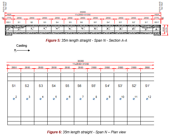
5.3 GEOMETRY GENERAL ARRANGEMENT – SPAN N
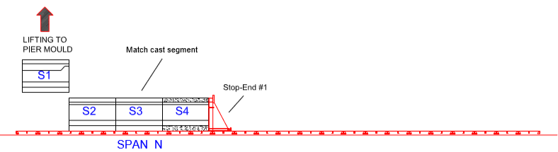
Note that pier segments are cast on the appropriate mould, which is the Short Line Pier Mould. For more details, refer to the Method Statement HCMC-261-CSYD-CWS-MST-00018 “Casting sequence – Short Line Pier Segment”).
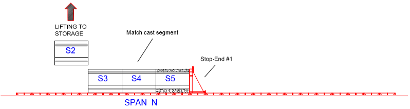
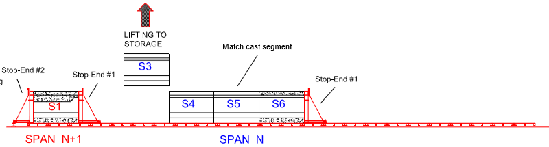
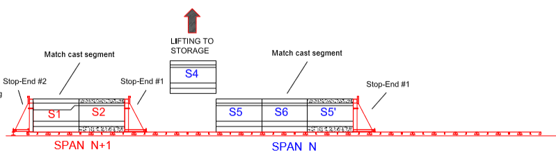
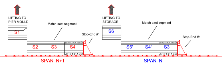
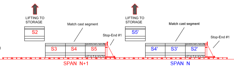
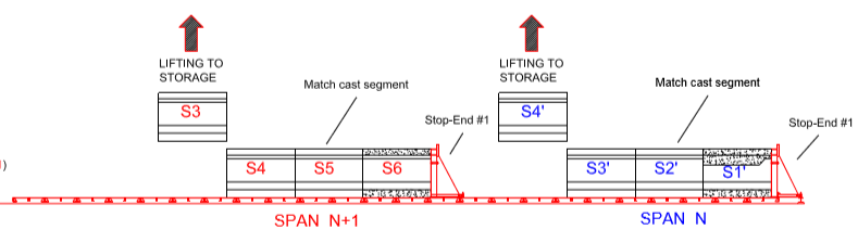
5.4 CINEMATIC MANUFACTURE OF PROCESS – SPAN N
DAY 1:
DAY 2:
DAY 3:
DAY 4:
DAY 5:
DAY 6:
DAY 7:
DAY 8:

DAY 9:
DAY 10:
DAY 11:
5.5 CONCLUSION
A total of 11 day cycle is required to achieve 11 typical segments of a 35m straight span.
6. ACTIVITY HOLD POINTS
Similar to the Hazard & Risk Assessments, activity hold points will be identified on the Method Statements related to each particular activity to be performed.
7. INSPECTION & RECORDS
Each Inspection & Records performed will be listed in the Inspection Test & Plan (ITP).