Method Statement for General Erection Works
1. INTRODUCTION
1.1 PURPOSE OF THE DOCUMENT
The purpose of this procedure is to outline General Arrangements, Construction Methodologies and other works related to the erection works
Where it is identified that there is a need to change the method of work due to unforeseen circumstances, then revision, authorisation and issue will follow the same procedure as the original
1.2 PROJECT DESCRIPTION
Ho Chi Minh City Urban Railway Construction Project – Ben Thanh – Suoi Tien section (Line 1), contract Package 2 consists of approximately 12 km long of elevated viaduct structures, erected by span-by-span Method. Precast viaduct segment elements will be erected and reassembled on site forming isostatic span using specific lifting equipment called Launching Girder / Launching Girder. In case erection can’t be done using Launching Girder, the falsework will be used.
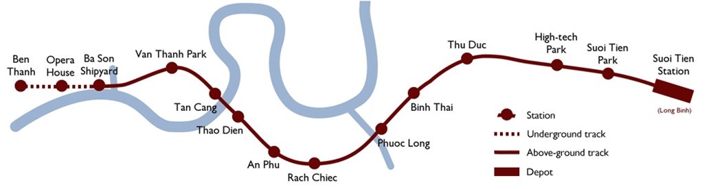
Figure 1: Line 1 – General Layout
1.3 SCOPE OF WORK
This procedure is developed for application in the scope of works and applies to the erection operations of the precast bridge of the HCMC Metro Project.
1.4 REFERENCES
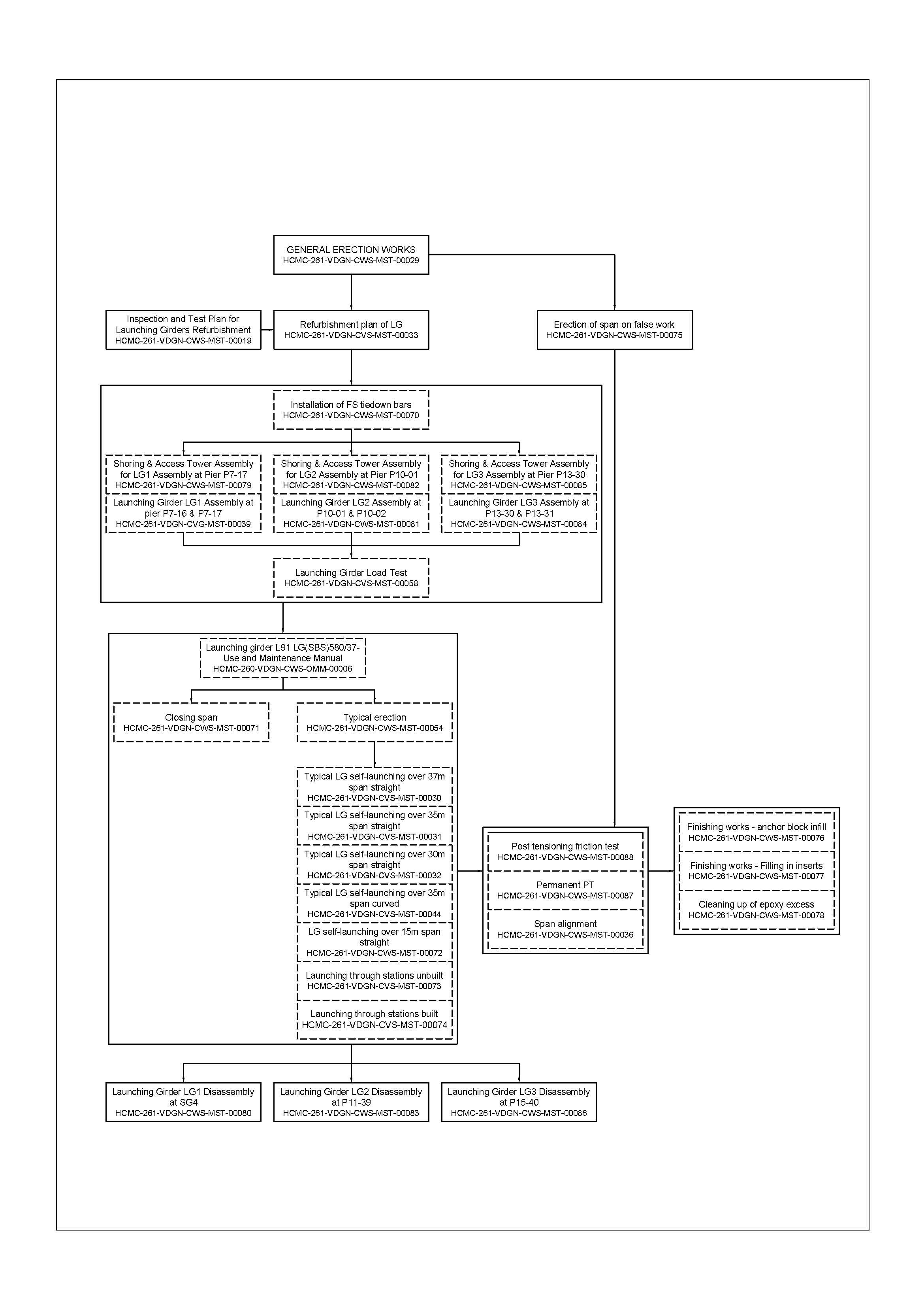
This procedure is formed by the following method statements:
| Method statements - Description | Document Ref. |
|---|---|
| General erection works | HCMC-261-VDGN-CWS-MST-00029 |
| Refurbishment plan of LG | HCMC-261-VDGN-CVS-MST-00033 |
| Installation of FS tie down bars | HCMC-261-VDGN-CWS-MST-00070 |
| Launching Girder LG1 Assembly at pier P7-16 & P7-17 | HCMC-261-VDGN-CVG-MST-00039 |
| Launching Girder LG2 Assembly at P10-04 & P10-05 | HCMC-261-VDGN-CWS-MST-00081 |
| Launching Girder LG3 Assembly at P13-17 & P13-18 | HCMC-261-VDGN-CWS-MST-00084 |
| Shoring & Access Tower Assembly for LG1 Assembly at Pier P7-17 | HCMC-261-VDGN-CWS-MST-00079 |
| Shoring & Access Tower Assembly for LG2 Assembly at Pier P10-04 | HCMC-261-VDGN-CWS-MST-00082 |
| Shoring & Access Tower Assembly for LG3 Assembly at Pier P13-17 | HCMC-261-VDGN-CWS-MST-00085 |
| Launching Girder load test | HCMC-261-VDGN-CVS-MST-00058 |
| Typical erection | HCMC-261-VDGN-CVS-MST-00054 |
| Typical LG self-launching over 37m span straight | HCMC-261-VDGN-CVS-MST-00030 |
| Typical LG self-launching over 35m span straight | HCMC-261-VDGN-CVS-MST-00031 |
| Typical LG self-launching over 30m span straight | HCMC-261-VDGN-CVS-MST-00032 |
| Typical LG self-launching over 35m span curved | HCMC-261-VDGN-CVS-MST-00044 |
| LG1 Launching back | HCMC-261-VDGN-CWS-MST-00072 |
| U-Girder Load Test | HCMC-261-VDGN-CWS-MST-00073 |
| Closing span | HCMC-261-VDGN-CWS-MST-00071 |
| Post tensioning friction test | HCMC-261-VDGN-CWS-MST-00088 |
| Permanent Post Tensioning | HCMC-261-VDGN-CWS-MST-00087 |
| Span alignment | HCMC-261-VDGN-CWS-MST-00036 |
| Finishing Works of filling in Inserts and Anchor Block Infill | HCMC-261-VDGN-CWS-MST-00076 |
| Finishing Works of filling Restrainer Bar Recess | HCMC-261-VDGN-CWS-MST-00077 |
| Self-Launching through Stations | HCMC-261-VDGN-CWS-MST-00074 |
| Launching Girder LG1 Dismantling at SG4 | HCMC-261-VDGN-CWS-MST-00080 |
| Launching Girder LG2 Dismantling in VD13 (P13-14 to P13-17) | HCMC-261-VDGN-CWS-MST-00276 |
| Launching Girder LG3 Dismantling in VD14 (P14-30 to P14-33) | HCMC-261-VDGN-CWS-MST-00217 |
All reference documents are intended to refer to the last issued revision.
1.5 DEFINITIONS
- Employer
Management Authority for Urban Railways, also called MAUR
- Method Statement
A work instruction detailing technical/engineering methodology for a particular activity including the Hazard Analysis & Risk Assessment.
- HRA (Hazard & Risk Assessment)
Identify all hazard & risk per activity, and reduce the probably of each risk by using different kind of solutions, such as: training for workers to prevent and inform them, inspection, check-list etc…
- ITP (Inspection & Test Plan)
The purpose of this procedure is to clearly identify all inspection, check-list and test which have to be done in order to respect with Quality & Safety requirements.
- Pre-casting yard (PCY)
Area used to manufacture and temporary store all precast segments.
- U-Section
Precast concrete section typically, U-shaped, consisting of a bottom slab, two side webs and lateral top flanges. It concerns all segment used for this project.
- Typical segment
The segments used in the central parts of the spans and between the pier segments. They are characterized by an almost constant shape.
- Pier segment
It defines the first and the last segment of the span, and which are positioned on a pier by means of bearings.
- Span
As span is consisted of 2 pier segments and several typical segments. Each pier segment is located at both end. The U section varies from 15 to 37m span length.
- Curved span
As span which horizontal alignment is not straight, minimum radius of curved span for this project is from 300m.
- Span by span method
This method of construction is applicable when the span is built by beginning at one pier and proceeding towards the next pier. This type of construction needs special equipment called “Launching Girder” by means of which the whole span is hung until longitudinal final post-tensioning (PT) would be applied.
- Closing span
The span to be erected adjacent to already built spans
- Erection Site
The site where the superstructure span is erected
- Superstructure
The super elevated concrete deck where the rails run; it is supported by concrete pier and has a variable span
- Self-launching
All the operations required to move the launching girder from the already built span to the next one
- Next span
The span to build after the self-launching of the equipment
- Post-tensioning
Post-tensioning is a method of reinforcing (strengthening) the U-girder span with high-strength steel strands as tendons.
- Bearing
Bearings are devices for transferring loads and movements from the span to the substructure and foundations.
- Grout
Grout is used to fill the duct after stressing the tendon.
- Launching Gantry / Launching Girder
The equipment for erecting the superstructure. It is provided with a hoisting winch for the segment handling and with a capstan system for the self-launching.
The launching gantries used for this project will be launching girder L91 LG(SBS)580⁄37 type – (580 tonnes lifting capacity, 37m maximum span length).
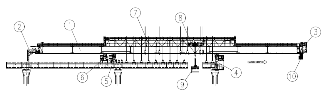
Figure 2: Launching Girder
Launching girder can be subdivided in main groups as follows:
| 1 | Main Girder | The main girder is the structural part of the equipment that bears the segment’s loads during the erection. Its structure is made of 2 girders connected together at the front and rear heads by relevant structures. Each steel box girder is composed of 9 rectangular box-type built up beams joint to each other by means of PT bars. Rails are fitted both on the upper side for the trolley of hoisting winch system, and on the lower side acting as runways for the girder during self-launching phase. On the lower side at the centre of each girder a rail beam is located to provide the anchorage of the main girder to the rear support or to the auxiliary support by means of hydraulic cylinders. The rail beam is also used as a guide for supports relocation during self-launching phases. On the upper side special plates are welded to provide the fixing of the hanging system. |
| 2 | Rear Head | It consists of a frame with a platform connected to the main girder on which: • the winch hoisting system is driven, • the trolley movement system is driven by means of the rear pulleys and counterweight system, • the support translation system is installed. The translation system allows the longitudinal movement of the supports during self-launching. The Rear Head platform houses the electric generator. |
| 3 | Front head | It consists of a frame with a platform connected to the main girder on which • the winch hoisting system is fixed, • the trolley movement system is driven by means of the front pulleys counterweight system, • the support translation system is driven. |
| 4 | Front Support | The front support is the structural part of the equipment which transfers the loads to the pier during the erection phases (whole span suspended to the equipment). It represents, together with the rear support, the main support bearing system of the equipment. Furthermore the front support together with the other two supports allows the self-launching of the equipment. The structure is made by 2 telescopic legs anchored at pier cap concrete level by means of anchoring bars. A transverse box-type beam is fixed on top of the legs. Two rails are provided on top of the transverse beam to allow the support movement on special slides by means of a hydraulic transversal step by step system. The support system consists of two frames (right and left) of 4 rollers with steel wheels (two under each box) fixed on hydraulic jacks with safety nuts which are used to lower the loads and to recover the deflection of the main girder during the erection of the spans. Two articulated arms are installed on each leg for moving the stressing jacks during the erection sequences. |
| 5 | Rear support | The rear support is the structural part of the equipment which transfers the loads to the deck during the erection phases (whole span suspended to the equipment). It represents, together with the front support, the main support bearing system of the equipment. Furthermore the rear support together with the other two supports allows the self-launching of the equipment. The structure is made of 4 hydraulic jacks with safety nuts fixed on 2 longitudinal beams under the transverse beam. Two rails are provided on top of the transverse beam to allow the support movement on special slides by means of a hydraulic transversal step by step system. The support system consists of two frames (right and left) of 4 rollers with steel wheels (two under each box) fixed on hydraulic jacks with safety nuts which are used to lower the loads and to recover the deflection of the Main girder during the erection of the span. On the rear support is fixed the main girder anchorage system acting by means of two hydraulic jacks on the rail beam fixed to the main girder. During the erection sequences (hanging of segments) the anchorage system must be engaged to the rear support. During the relocation of supports and self-launching sequences, the anchorage system can be engaged to the rear support or to the auxiliary support. |
| 6 | Auxiliary support | The auxiliary support is the service support of the equipment and it is used during the self-launching sequences only. The auxiliary support transfers the loads to the deck. The structure is made of 4 hydraulic jacks with safety nuts fixed on 2 longitudinal beams under the transverse beam. Two rails are provided on top of the transverse beam to allow the support movement on special slides by means of a hydraulic transversal step by step system. The support system consists of two frames (right and left) of 4 rollers with steel wheels (two under each box). On the auxiliary support is fixed the second main girder anchorage system acting by means of two hydraulic jacks on the rail beam fixed to the main box. Only during the self-launching sequences the anchorage system can be engaged to the auxiliary support. |
| 7 | Hanging system | The purpose of the hanging system is to position and hold the span segments during their erection. It consists of a series of beams installed on the main girder boxes that fit the high strength hanging bars, a rope adjustable systems and spreader beams for connecting the U segments. A counterweight system with ropes and pulleys allows at the completion of the erection to lift the bars and the other components in order to leave a clearance between the spreader beam and the front support transverse beam during the self-launching sequences. |
| 8 | Lifting trolley | The lifting trolley is the movable group which houses the lifting pulleys and it moves longitudinally on the upper rails of the boxes by means of two capstans during the segment erection. Furthermore it houses pulleys and devices for the anchoring of the launching girder during self-launching operations. When the trolley is anchored to the rear support or to the auxiliary support the capstans are used for moving the main girder. |
| 9 | Spreader Beam and lifting block | The spreader beam is the component that together with the hoisting winch allows the handling of pre-cast segments during erection of the viaduct. It consists of a telescopic equalizer beam that moves the bearing plates under the U segment inner noses. The spreader beam is equipped with a hydraulic motor with reduction gear and chain allowing a rotation +/- 105° and with hydraulic jacks for adjusting the longitudinal and transversal slopes. |
| 10 | Service platform | The service platform allows personnel to reach the front support for service purposes moving on wheels under the main girder. It is connected to the support movement system. |
- Falsework
Temporary structure that the span will be erected on. Falsework supports the self-weight of span, working load. It will be removed after the self-weight of span transfer to the pier.
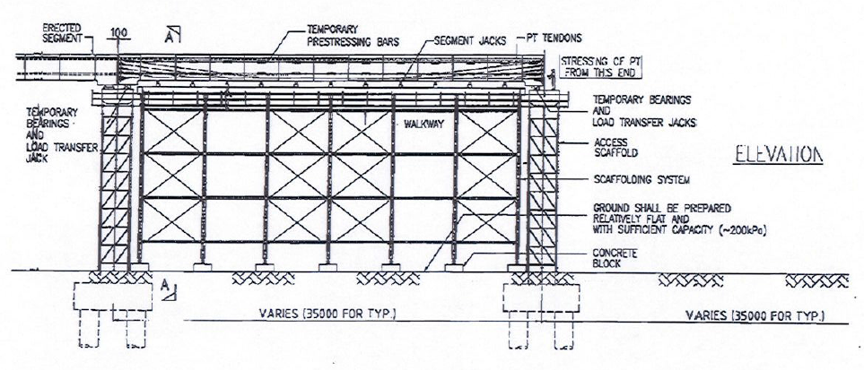
Figure 3: Example of falsework system
2. SAFETY & ENVIRONMENTAL RISKS
2.1 HAZARD ANALYSIS & RISK ASSESSMENT
Hazards Analysis and Risks assessment are carried out and attached in each Method Statement. This document will identify all the hazards to ensure adequate control measures and strategies are in place to mitigate as much as possible the risks.
All personnel carrying out the work will be properly trained by experienced supervision. Besides, all personnel shall wear the appropriate PPE (Personal Protective Equipment), such as Safety shoes, safety helmet and safety harness if required.
2.2 TOOLS AND EQUIPMENT
All tools & equipment shall be in safe condition before utilisation and fit for its purpose. Where applicable, before each shift, equipment shall be visually checked for the mechanical and structural soundness.
2.3 EMERGENCY RESPONSE
In the event of an accident/incident, response will carried out in the appropriate procedure, such as:
- Remedial Actions, proposing actions to ensure that the Accident/Incident will be fully fixed, as required, managed by the Responsible within a target date.
- Preventive Actions, proposing actions to ensure that the Accident/Incident will never happen again, including for example: Toolbox Meeting (TBM) held by the Safety Officer to ensure that Site Team (Workers, Supervisors & Engineers) fully understand methods & risks.
Prestart and Toolbox Meeting will reinforce safety requirements prior to commencement of the work.
3. CONSTRUCTION RESOURCES
In principle every type of work involves the following resources:
3.1 PERSONNEL
The personnel involved are such as:
- Erection Manager
- General Superintendent
- Site engineers
- QA/QC Engineers
- Safety Officers
- Supervisors
- Surveyors
- LG operator, crane operator
- Skilled workers
- Electricians
- Mechanics
3.2 PLANT AND TOOLS
The following equipment shall be used for erection works:
- Launching Girder
- Hoisting equipment
- Jack
- Cherry picker
- Mobile cranes
- Generators
- Spanners
- Lever block
- Setting out instruments (Total station, auto-level, etc.)
- Strand pusher
- Guide pipe
- H-speed abrasive cutter or Hydraulic cutter
- Strand coil dispenser
- Strand Bullets
- Walkie-Talkie
- Pressure gauge
- Grout mixer / Pump
- Air compressor
- Grout hose
- Weighting scale
- Cube moulds
- Flow cone
- Stop watch
- Thermometer
- Water tank
- Hand tools
- Chains / slings / shackle
- Trailers (for segment delivery)
- Lifting frame for segment (also called “spreader beam”)
- Concrete bucket
- Electric tools
- Safety signs
- Concrete block
- Scaffolding
- Temporary support tower
- Finishing platform
- Falsework
- Others
3.3 MATERIALS
- Post-tensioning elements (strand, anchorage, ducting…)
- Grout
- Epoxy
- Lubricants
- Hydraulic oil
- Diesel oil
- Water, woods, steel, shim etc.
4. CONSTRUCTION PROCESS
4.1 SPAN ERECTION USING LAUNCHING GIRDER
Ho Chi Minh City (HCMC) urban railways project: Ben Thanh – Suoi Tien section Line 1 will be constructed by span by span precast segmental erection method for majority viaduct with Overhead Launching Gantries (LG).
The segments are transported from the pre-casting yard and delivered to the erection site under each LG by trailer. A Launching Girder supported at both extremity of the span to be erected and equipped with a lifting spreader beam connected to a winch trolley will hoist and moved to the required position the different precast segments that compose the span to be built. After all the segments are suspended to form a span, they will be tightened together by post tensioning. The span will be transferred from the Launching Girder to the piers and aligned. The launching equipment will move forward to erect the next span.
CONSTRUCTION CYCLE:
- Self-launching to the span will be erected
- Segment delivery and lifting
- Segment positioning and hanging
- Relocation of segments
- Apply of epoxy
- Stressing of temporary PT
- Load transfer, permanent PT, grouting and span alignment
- Finishing work
LG KINEMATICS / SELF-LAUNCHING:
Span is erected and LG is ready to be launched
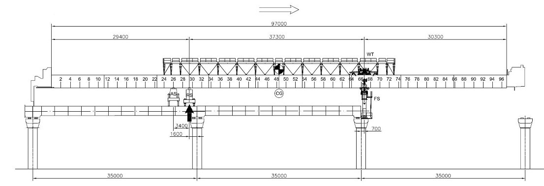
Figure 4: Ready to be launched
- Relocate rear support (RS)
- Disengage front support (FS) and transfer load to RS
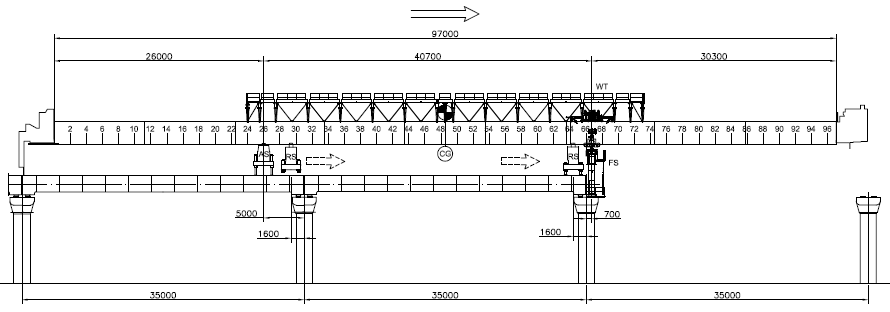
Figure 5: Move and transfer load to RS
Launch LG partially
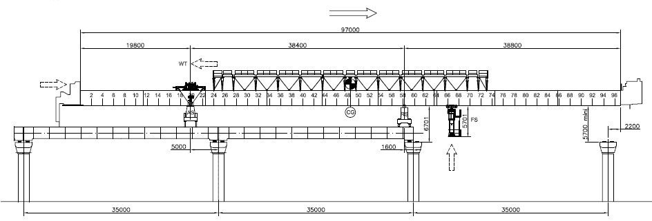
Figure 6: Launch LG partially
- Relocate FS
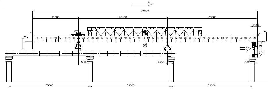
Figure 7: Relocate front support (FS)
- Engage FS
- Launch LG partially
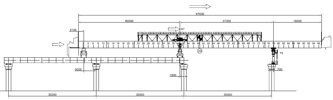
Figure 8: Engage FS and launch LG
- Disengage auxiliary support (AS)
- Relocate AS
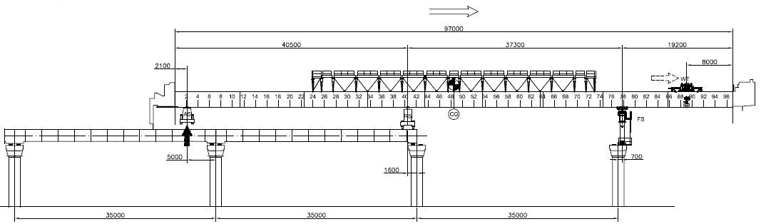
Figure 9: Disengage auxiliary support (AS) and relocate AS
- Launch LG to final position
Figure 10: Launch LG to final position
4.2 SPAN ERECTION ON FALSEWORK
The span will be erected on the falsework system where the Launching Girder will not be able to be used.
CONSTRUCTION CYCLE:
- Install falsework system
- Lifting and placing of segments onto the falsework system
- Segments matching, apply of epoxy and stressing of temporary PT
- Stressing of PT tendons, transfer the span to permanent bearing
- Finishing work
5. METHODOLOGY
The construction methodology consists of:
5.1 ASSIGNMENT, SAFETY INDUCTION & COMPETENCY OF PERSONNEL
All site personnel shall attend a Health & Safety Environment (HSE) induction training session. Induction will be provided by the Safety Officer to ensure they are fully awarded and understand all Safety requirements. Site engineers & Supervisors shall ensure that the work is carried out by adequately trained workers.
5.2 HAZARD ANALYSIS & RISK ASSESSMENT
Hazard Analysis & Risk Assessment will be regularly reviewed by both erection and HSE Department to ensure that all the hazards have been identified and adequate control measures are in place.
5.3 PLANT & EQUIPMENT CHECKS COMPLETED
At the beginning of each shift, all equipment shall be visually inspected for mechanical & structural soundness. Damaged plant and equipment shall not be used and will be tagged out of service until repaired to manufacturer’s requirements or removed from site.
5.4 REFURBISHMENT PLAN OF LG
Procedures related to refurbishment plan of Launching Girder shall refer to this detailed method statement in document reference: HCMC-261-VDGN-CVS-MST-00033
5.5 ITP FOR LAUNCHING GIRDER REFURBISHMENT
Procedures related to launching girder refurbishment inspection and test plan shall refer to this detailed method statement in document reference: HCMC-261-VDGN-CWS-PLN-00014
5.6 INSTALLATION OF FS TIE DOWN BARS
Procedures related to installation of FS tie down bars shall refer to this detailed method statement in document reference: HCMC-261-VDGN-CVS-MST-00070
5.7 LAUNCHING GIRDER ASSEMBLY
Procedures related to Launching Girder LG1 assembly at pier P7-16 & P7-17 shall refer to this detailed method statement in document reference: HCMC-261-VDGN-CVG-MST-00039 Procedures related to Launching Girder LG2 assembly at P10-01 & P10-02 shall refer to this detailed method statement in document reference: HCMC-261-VDGN-CWS-MST-00081 Procedures related to Launching Girder LG3 assembly at P13-31 & P13-32 shall refer to this detailed method statement in document reference: HCMC-261-VDGN-CWS-MST-00084
5.8 SHORING & ACCESS TOWER ASSEMBLY
Procedures related to shoring & access tower assembly for LG1 assembly at pier P7-17 shall refer to this detailed method statement in document reference: HCMC-261-VDGN-CWS-MST-00079 Procedures related to shoring & access tower assembly for LG2 assembly at pier P10-01 shall refer to this detailed method statement in document reference: HCMC-261-VDGN-CWS-MST-00082 Procedures related to shoring & access tower assembly for LG3 assembly at pier P13-30 shall refer to this detailed method statement in document reference: HCMC-261-VDGN-CWS-MST-00085
5.9 LAUNCHING GIRDER LOAD TEST
Procedures related to Launching Girder load test shall refer to this detailed method statement in document reference: HCMC-261-VDGN-CVS-MST-00058
5.10 USE AND MAINTENANCE MANUAL
Procedures related to Launching Girder LG1, LG2, LG3 use and maintenance manual shall refer to this detailed method statement in document reference: HCMC-261-VDGN-CWS-OMM-00006
5.11 TYPICAL ERECTION
Procedures related to typical erection shall refer to this detailed method statement in document reference: HCMC-261-VDGN-CVS-MST-00054
5.12 ERECTION OF SPAN ON FALSEWORK
Procedures related to erection of span on falsework shall refer to this detailed method statement in document reference: HCMC-261-VDGN-CWS-MST-00075
5.13 LG SELF-LAUNCHING
Procedures related to typical LG self-launching over 37m span straight shall refer to this detailed method statement in document reference: HCMC-261-VDGN-CVS-MST-00030 Procedures related to typical LG self-launching over 35m span straight shall refer to this detailed method statement in document reference: HCMC-261-VDGN-CVS-MST-00031 Procedures related to typical LG self-launching over 30m span straight shall refer to this detailed method statement in document reference: HCMC-261-VDGN-CVS-MST-00032 Procedures related to typical LG self-launching over 35m span curved shall refer to this detailed method statement in document reference: HCMC-261-VDGN-CVS-MST-00044 Procedures related to LG self-launching over 15m span straight shall refer to this detailed method statement in document reference: HCMC-261-VDGN-CWS-MST-00072
5.14 LAUNCHING THROUGH STATION
Procedures related to launching through stations unbuilt shall refer to this detailed method statement in document reference: HCMC-261-VDGN-CWS-MST-00073 Procedures related to launching through stations built shall refer to this detailed method statement in document reference: HCMC-261-VDGN-CWS-MST-00074
5.15 CLOSING SPAN
Procedures related to closing span shall refer to this detailed method statement in document reference: HCMC-261-VDGN-CWS-MST-00071
5.16 POST TENSIONING FRICTION TEST
Procedures related to post tensioning friction test shall refer to this detailed method statement in document reference: HCMC-261-VDGN-CWS-MST-00088
5.17 PERMANENT PT
Procedures related to permanent PT shall refer to this detailed method statement in document reference: HCMC-261-VDGN-CWS-MST-00087
5.18 SPAN ALIGNMENT
Procedures related to span alignment shall refer to this detailed method statement in document reference: HCMC-261-VDGN-CWS-MST-00036
5.19 FINISHING WORKS
Procedures related to finishing works – anchor block infill shall refer to this detailed method statement in document reference: HCMC-261-VDGN-CWS-MST-00076 Procedures related to finishing works – filling in inserts shall refer to this detailed method statement in document reference: HCMC-261-VDGN-CWS-MST-00077 Procedures related to cleaning up of epoxy excess shall refer to this detailed method statement in document reference: HCMC-261-VDGN-CWS-MST-00078
5.20 LAUNCHING GIRDER DISASSEMBLY
Procedures related to Launching Girder LG1 disassembly at SG4 shall refer to this detailed method statement in document reference: HCMC-261-VDGN-CWS-MST-00080 Procedures related to Launching Girder LG2 disassembly at P11-39 shall refer to this detailed method statement in document reference: HCMC-261-VDGN-CWS-MST-00083 Procedures related to Launching Girder LG3 disassembly at P15-40 shall refer to this detailed method statement in document reference: HCMC-261-VDGN-CWS-MST-00086
6. ACTIVITY HOLD POINTS
Hold points will be identified in the Inspection & test Plan.
7. INSPECTION & RECORDS
All Inspection / check-lists & documents records will be identified in the Inspection & test Plan.
8. ATTACHMENTS: TABLE RELATED TO ERECTION WORKS