Method Statement for Segment Marking at Precasting Yard
1. INTRODUCTION
1.1 PURPOSE OF THE DOCUMENT
The purpose of this procedure is to describe the procedure regarding the marking of precast segments, prior to their transport to their erection location, and ensure that all works will be conducted safely in accordance with the drawings and the project specifications.
1.2 PROJECT DESCRIPTION
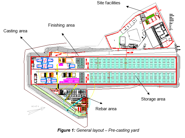
Ho Chi Minh City Urban Railway Construction Project - Ben Thanh - Suoi Tien section (Line 1), contract Package consists of approximately 12 km long of elevated viaduct structures, erected by span-by-span Method.
1.3 SCOPE OF WORK
This procedure is developed for application in the scope of works and applies to all precast segments composing the viaduct superstructure works of the HCMC Metro Project.
1.4 REFERENCES
Specifications:
- Reference is made to clause 12.4.1: “Precast Segment Casting” (15) “Marking of segments” of Outline Construction Specification Package 2: Civil (Elevated & Depot).
Method Statement:
- Method Statement “Precast segment production - Short Line Typical mould” - HCMC-261-CSYD-CWS-MST- 00015.
All reference documents are intended to refer to the last issued revision.
1.5 DEFINITIONS
In this Terms & conditions the meanings assigned to words and expressions shall be the following:
- “Marking” means the process of giving of a specific mark for each segment in order to identify each one during the erection process.
Further definitions have been given in Section 1.5 “Definitions” of the method Statement “General precasting works at precasting yard” HCMC-261-CSYD-CWS-MST- 00012.
2. SAFETY & ENVIRONMENTAL RISKS
2.1 HAZARD ANALYSIS & RISK ASSESSMENT
Hazards Analysis and Risks assessment are carried out and attached in each Method Statement. This document will identify all the hazards to ensure adequate control measures and strategies are in place to mitigate as much as possible the risks (Refer to appendix A).
All personnel carrying out the work will be properly trained by experienced supervision. Besides, all personnel shall wear the appropriate PPE (Personal Protective Equipment), such as Safety shoes, safety helmet and safety harness if required.
2.2 TOOLS AND EQUIPMENT
All tools & equipment shall be in safe condition before utilisation and fit for its purpose. Where applicable, before each shift, equipment shall be visually checked for the mechanical and structural soundness.
2.3 EMERGENCY RESPONSE
In the event of an accident/incident, response will carried out in the appropriate procedure, such as:
- Remedial Actions, proposing actions to ensure that the Accident/Incident will be fully fixed, as required, managed by the Responsible within a target date.
- Preventive Actions, Tool-Box Talk (TBT) will be held by the Safety Officer for Site Personnel. It will reinforce safety requirements prior to commencement of the work. and will ensure that Site personnel fully understand method & risk.
3. CONSTRUCTION RESOURCES
In principle every type of work involves the following resources:
3.1 PERSONNEL
The personnel involved are such as:
- Site engineers
- Supervisors
- Workers
3.2 PLANT AND TOOLS
The following equipment shall be used for purpose of segment concreting works:
- Paint brush or ink pad and stamp
- Numerical and alphabet template
3.3 MATERIALS
- Emulsion paint (Red color)
4. MARKING PROCEDURE
4.1 PRINCIPLE
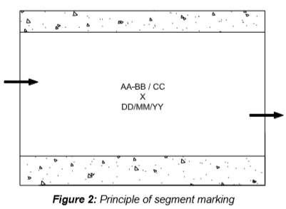
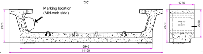
The segment has to be marked on one side of the internal web only. Final marking shall be made by indelible marking (water and sun proof). The alphabet or numerical letters marking are approximately 70mm high, and are painted by means of a spray and template. 4 data have to be indicated on the internal part of the left web at approximately mid segment as per the increasing chainage direction, as illustrated in figure 2.
- Span name: AA-BB / CC
- AA: Section
- BB: Down-chainage pier number
- CC: Up-chainage pier number
All following reference numbers are intended to refer to the last issued shop drawing related to the span.
- Segment number: X
“X” is the position of the segment in the span. The number 1 for every span starts from down-chainage and the number increases towards up-chainage.
- Casting date: DD/MM/YY
The date should be indicated with the format Day (DD) / Month (MM) / Year (YY).
- Arrow across segment:
The arrow should be marked and follows the increasing chainage direction, located at different level of segment side.
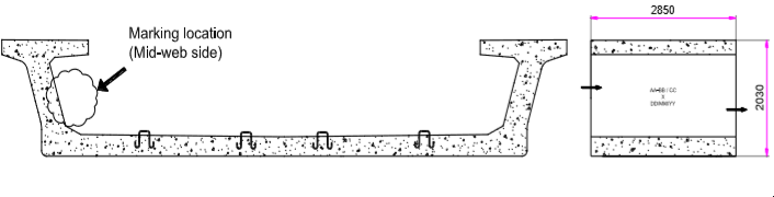
4.2 MARKS ON MID-WEB SIDE - TYPICAL SEGMENT
4.3 MARKS ON MID-WEB SIDE - TYPICAL SEGMENT “S1”
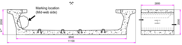
4.4 MARKS ON MID-WEB SIDE - PIER SEGMENT “ES1”
4.5 CHRONOLOGY
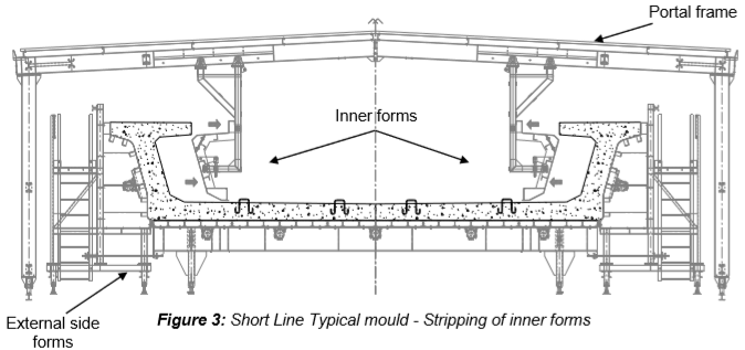
The marking has to be performed straightaway after stripping of the inner forms as shown on figure 3.
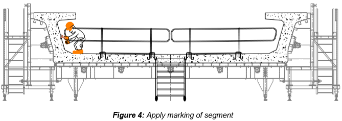
Make sure the marking of segment is carried out prior to remove the Match-Cast (M/C) segment, used to cast the fresh-cast (F/C) segment to be marked, from its M/C position in order to be able to paint the arrow on both M/C and F/C segments.
Supervisor shall ensure that the identification number is marked clearly and properly on the right location mentioned as shown on the figure 4.
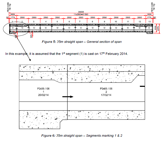
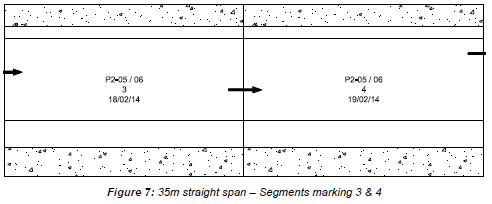
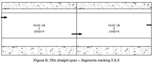
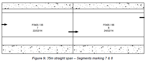
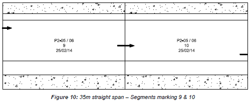
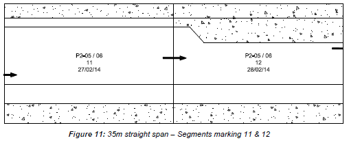
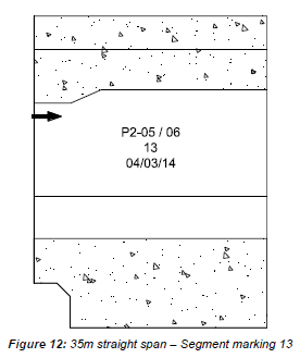
4.6 SEGMENT MARKING EXAMPLE
The 35m straight span, called P2-05 / P2-06, between the pier P2-05 and P2-06 including 11 typical and 2 pier segments (total 13 Nos), and has to be marked as follows:
5. ACTIVITY HOLD POINTS
Hold points will be identified in the Inspection & Test Plan.
6. INSPECTION & RECORDS
All Inspection / check-lists & documents records will be identified in the Inspection & Test Plan