Method Statement for Segment Lifting & Handling Works
1. INTRODUCTION
1.1 PURPOSE OF THE DOCUMENT
The purpose of this document is to describe the procedure of operation to be followed for the lifting of concrete precast segments, and ensure that all works will be conducted safely in accordance with the technical drawings, and the project specifications.
1.2 PROJECT DESCRIPTION
Ho Chi Minh City Urban Railway Construction Project – Ben Thanh – Suoi Tien section (Line 1), contract Package 2 consists of approximately 12 km long of elevated viaduct structures, erected by span-by-span Method.
1.3 SCOPE OF WORK
This method statement defines the lifting of all precast concrete segments at the precasting yard, composing the viaducts of HCMC Line 1 – Metro Project.
- Included:
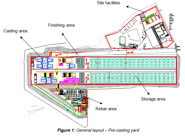
- Transfer segment from mould area to finishing area
- Transfer segment from finishing to storage area
- Transfer segment from storage area to trailers for segment delivery
- Transfer 1st of span segment from mould to another mould
- Excluded:
- Lifting segment for span erection
1.4 REFERENCES
- Specifications:
- Reference is made to clause 12.4.2 “Precast segment handling, storage and transport” from Outline Construction Specification Package 2: Civil (Elevated & Depot).
- Method Statement:
- Method Statement “Segment storage & stacking” – HCMC-261-CSYD-CWS-MST-00026
- Method Statement “Segment delivery & transportation” - HCMC-261-CSYD-CWS-MST- 00027
- Drawing:
- Technical drawing “Precasting yard - Lifting of segment - Steel plate” FVR-TEC-DWG-3140-020
All reference documents are intended to refer to the latest issued revision.
1.5 DEFINITIONS
In this Terms & conditions the meanings assigned to words and expressions shall be the following:
- “PCY” means Precasting yard
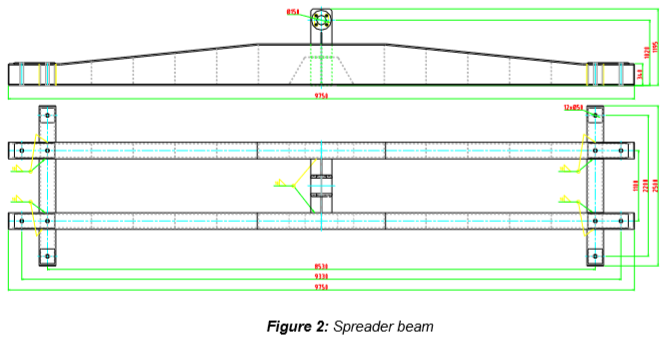
- “Segment lifting frame” or “Spreader beam” means the frame that is required for the lifting and transporting of the complete segment from the mould either to the finishing area or storage area. This equipment shall be designed so that there is no permanent distortion of the segment either during lifting, transport or placing on trailer prior to deliver on site.
Further definitions have been given in Section 1.5 “Definitions” of the Method Statement “General precasting works at precasting yard” - HCMC-261-CSYD-CWS-MST-00012.
2. SAFETY & ENVIRONMENTAL RISKS
2.1 HAZARD ANALYSIS & RISK ASSESSMENT
Hazards Analysis and Risks assessment are carried out and attached in each Method Statement. This document will identify all the hazards to ensure adequate control measures and strategies are in place to mitigate as much as possible the risks (Appendix C).
All personnel carrying out the work will be properly trained by experienced supervision. Besides, all personnel shall wear the appropriate PPE (Personal Protective Equipment), such as safety shoes, safety helmet and safety harness if required.
2.2 TOOLS AND EQUIPMENT
All tools & equipment shall be in safe condition before utilisation and fit for its purpose.
2.3 EMERGENCY RESPONSE
In the event of an accident/incident, response will be carried out in the appropriate procedure, such as:
- Remedial Actions, proposing actions to ensure that the Accident/Incident will be fully fixed, as required, managed by the responsible within a target date.
- Preventive Actions, proposing actions to ensure that the Accident/Incident will never happen again, including for example: Toolbox Meeting (TBM) held by the Safety Officer to ensure that Site Team (Workers, Supervisors & Engineers) fully understand methods & risks.
3. CONSTRUCTION RESOURCES
3.1 PERSONNEL
The personnel involved are such as:
- PCY Supervisor
- Storage supervisor
- Gantry crane Operator (50 tons)
Riggers
3.2 PLANT AND TOOLS
The following equipment shall be used for the purpose of segment handling:
- Gantry crane
- Spreader beam
- Slogging wrench for nut of 32mm diameter
- Sledge hammer
3.3 MATERIALS (DEXTRA OR EQUIVALENT)
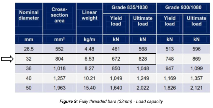
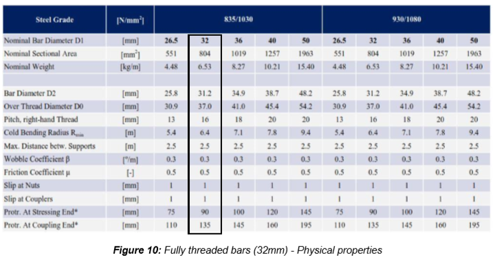
- Fully threaded bars (32mm diameter)
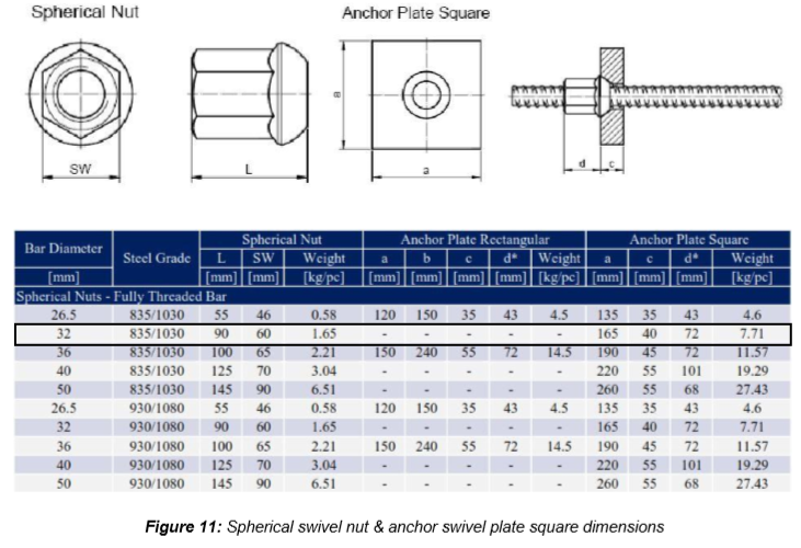
- Spherical swivel nut (32mm diameter)
- Anchor swivel plate square (32mm diameter)
4. CONSTRUCTION PROCESS
4.1 PRELIMINARY
After completion of segment manufacturing, once the concrete reach 25MPa, the segment can be lifted. 25MPa shall be confirmed by Main Contractor.
Then, the segment is lifted using a spreader beam, using 4 stress bar through designated lifting holes. On the spreader beam, several locations of lifting holes are available, depending of the type of segment to lift.
4.2 FIXING OF THE SPREADER BEAM ON THE SEGMENT
The following sub-sections outline the process which typically accomplishes the setting of the spreader beam in place on the precast typical and pier segments:
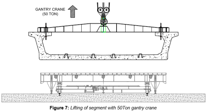
1- The spreader beam is set up by the 50 Ton gantry crane around 10mm above its final location on the segment to be lifted.
2- The spreader beam must visually hanged as much as possible aligned with the transversally axis of the segment.
3- Carefully, the 50Ton gantry crane is used to lower down the spreader beam until it’s in contact with segment’s top flange. Gantry crane operator shall be assisted by rigger.
4- Segment tightening:
- The 4 fully threaded bars DEXTRA or equivalent (Appendix A) are inserted through the 4 designated lifting holes to connect typical / pier segment with the spreader beam as shown below:
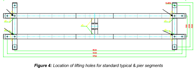
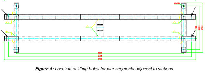
For pier segment near stations, the following lifting holes must be used due to the reduction of top flange’s dimension.
- Spherical swivel nut and anchor swivel plate square (32mm diameter) are installed below the top flange and above the spreader beam.
- A steel plate shall be used as wedge between the swivel plate and concrete at the bottom of flange.
- A rubber shall also be fixed to the bottom of spreader beam to avoid friction due to located load points between the spreader beam and the top of concrete flange.
- The 4 hanging bars are manually tightened using a wrench and a hammer for the last checking.
Stress bar shall be visually checked of any sign of bend, tread damage or any other defect EACH TIME it is used for connecting the segment to the spreader beam. All necessary safety measures shall be taken during lifting and transporting the segments, including:
- During lifting and moving with segment, speed for winching up or lowering down of 50Ton gantry crane shall be controlled in a safe manner by the operator and operated in low speed.
- Segment lifting path shall be always kept clear of any worker or remedial works. Workers have to stop working and move out of the lifting path prior to segment lifting.
- Segment shall be handled in full care to prevent any damage, especially on the shear keys and the match-catch surfaces.
4.3 RELEASE OF SEGMENT
Prior to transfer segment to finishing area, the following steps have to be carried out:
- The segment shall be placed on three appropriated concrete support blocks.
- When the segment is set down, remove threaded bars, plates and nuts (32mm diameter)
- The spreader is then lifted from the segment carefully to avoid any damage to the segment
5. ACTIVITY HOLD POINTS
Activity related to concrete strength for segment lifting will be identified in the Inspection & Test Plan. Refer to the ITP “Precast segment production”
6. INSPECTION & RECORDS
All Inspection / check-lists related to concrete strength for segment lifting will be identified in the Inspection & test Plan. Refer to the ITP “Precast segment production”
7. ATTACHMENTS
7.1 APPENDIX A: DEXTRA PRE-STRESSING BARS SYSTEM
- Fully threaded bars (Grade 835⁄1030)