Method Statement for Precast Segment Remedial Works
1. INTRODUCTION
1.1 PURPOSE OF THE DOCUMENT
The purpose of this procedure is to describe the repairing procedure for all precast defects occurred during production & handling of segment in precasting yard, and ensure that all works will be conducted safely in accordance with the Project specifications.
1.2 PROJECT DESCRIPTION
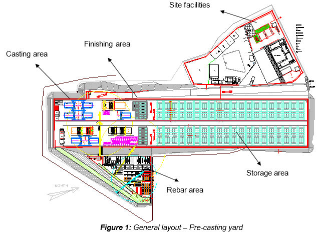
Ho Chi Minh City Urban Railway Construction Project – Ben Thanh – Suoi Tien section (Line 1), contract Package 2 consists of approximately 12 km long of elevated viaduct structures, erected by span-by-span Method.
1.3 SCOPE OF WORK
This method statement mentions the specialized remedial works for segment in precasting yard. This procedure details the sequence of work for viaduct segment to different category of defects, such as:
- Blowholes
- Spalled concrete edges
- Honeycombs and voids
- Cold joint
- Cracks
The following categories of defects are not concerned in this procedure and will be subjected to a Non-Conformance Report.
- Internal & external PT component defects
- Geometry defects
- CP3 inserts
- Drainage inserts
- Cross conduit connectors & mast support inserts
- Lifting holes
- Pedestal
1.4 REFERENCES
- Specifications
- Reference is made to clause 5.16 “Patching and Repairs” Section 5-22 of 23 from Outline construction specification – Package 2: Civil (Elevated & Depot)
- Other
- HCMC-SMI-270-003-A - Method Statement for Repair of Concrete Surface Defects and Cracks
1.5 DEFINITIONS
In these Terms & conditions the meanings assigned to words and expressions shall be the following:
- “PCY” means the Precasting yard
- “Repairing works” means the process of repairing (if needed) the concrete surface exposed.
- “Blowhole” means a form surface air pocket void
- “Honeycomb” means a void in concrete, a loss of fines or other material from between the aggregate particles or larger volume of lost material.
- “Cracks” means the structural or non-structural chinks in concrete surface, which are classified by the crack width.
2. SAFETY & ENVIRONMENTAL RISKS
2.1 HAZARD ANALYSIS & RISK ASSESSMENT
Hazards Analysis and Risks assessment are carried out and attached in this Method Statement. This document will identify all the hazards to ensure adequate control measures and strategies are in place to mitigate as much as possible the risks (Appendix A).
All personnel carrying out the work will be properly trained by experienced supervision. Besides, all personnel shall wear the appropriate PPE (Personal Protective Equipment), such as Safety shoes, safety helmet, working gloves and safety harness if required.
2.2 TOOLS AND EQUIPMENT
All tools & equipment shall be in safe condition before utilisation and fit for its purpose.
2.3 EMERGENCY RESPONSE
In the event of an accident/incident, response will carried out in the appropriate procedure, such as:
- Remedial Actions, proposing actions to ensure that the Accident/Incident will be fully fixed, as required, managed by the Responsible within a target date.
- Preventive Actions, proposing actions to ensure that the Accident/Incident will never happen again, including for example: Toolbox Meeting (TBM) held by the Safety Officer to ensure that Site Team (Workers, Supervisors & Engineers) fully understand methods & risks.
Prestart and Toolbox talk will reinforce safety requirements prior to commencement of the work.
3. CONSTRUCTION RESOURCES
In principle every type of work involves the following resources:
3.1 PERSONNEL
The personnel involved are such as:
- Site engineer
- Quality engineer
- Supervisor
- Foreman
- Workers
3.2 PLANT AND TOOLS
- Measuring tape, chalk
- Electric tools
- Hand tools
- Mobile staircase (if necessary)
- Mobile scaffolding platform (if necessary)
- Chains or slings (if necessary)
- Heavy duty drill
- Grinder
3.3 MATERIALS
Products shall be submitted through Approval Of Material procedure.
- Blowhole filler FOSROC Renderoc BF2, BASF Emaco R907 PLUS, Sika Refit 2000
- Micro concrete FOSROC Renderoc LAXtra, BASF Emaco S23 NB
- Repair grout FOSROC Renderoc HS, BASF Emaco S88 CT, Sikagrout 212-11, Sikagrout 214-11
- Epoxy injection FOSROC Nitofill LV, Sikadur 752
Other products may be submitted and use upon approval.
4. REMEDIAL WORKS PROCESS
4.1 GENERAL
The defects on all precast can be classified into 3 categories according to the consequences the defects may have:
- Category A: Damage not requiring repair
- Category B: Damage requiring repair
- Category C: Damage requiring the Non Conformance Report (NCR). All type of damage (insufficient concrete cover included) not described under categories A&B will be subject to a NCR prepared by SCC. NCR will report the investigation done around the defect, list preventive action to be implemented to avoid the defect to happen again and propose a corrective action. NCR will be submitted to Contractor approval before proceeding with the repair works.
4.2 CATEGORY A: DAMAGE NOT REQUIRING REPAIR
4.2.1 BLOWHOLES & MINOR GROUT LOSS
| DESCRIPTION |
|---|
| Localized air pockets and minor grout loss less than 5 mm in depth on all viaduct segments do not require repair. The blowholes must have less than 10mm diameter. The number can’t exceed 15 blowholes of more than 10mm diameter per m2 on the external surface. |
4.2.2 SPALLED CONCRETE
| DESCRIPTION |
|---|
| Localized damage may occur on any viaduct segment edge either during handling or during stripping of formwork. Limited damage on any viaduct segment edge which does not violate cover requirements does not require repair. The limit is as follows: Spalled edges at the bottom slab, web and at the top flange of the segment which occur during stripping and bond breaking of the formwork less than 20mm in depth do not require repair. Defect dimension check will be done on every viaduct segment by the foreman of each production line. “Any more than one (1) spall in one (1) face of a segment with less than one (1) meter apart it shall be repaired and any one (1) single spall that has one (1) side dimension greater than 20mm shall be repaired” Method in Category B shall be applied. |
4.2.3 CRACKS
| DESCRIPTION |
|---|
| Cracks on all viaduct segment surfaces with a width 0.2mm and depth not exceeding the top layer of reinforcement, do not require repair. |
4.3 CATEGORY B: DAMAGE REQUIRING REPAIR
4.3.1 BLOWHOLES & SURFACE SPALLING
| DESCRIPTION | REPAIR ACTION |
|---|---|
| Localized blowholes and surface spalling more than 5mm in depth and depth not exceed 10mm shall be repaired. For larger areas or deeper damage use the repair method of Section 4.3.4 “Honeycombs and voids”. Excluded from this category the shear keys side surface for the viaduct segment: according to the previous description no repair shall be done. Defect dimension check will be done on every viaduct segment by the foreman of each production line. |
Criteria: 5mm < damage depth < 10mm Number of blowholes > 15 numbers of more than 10mm dia. per m2 Materials: - FOSROC Renderoc BF2 or, - BASF EMACO R907 PLUS or, - Sikagrout 212-11 or, - Sikagrout 214-11 or, - Sika Refit 2000 or, - Equivalent product Surface finish to be consistent with steel float finish and repair to be smooth and level with surrounding surface. Instructions: Applications should be strictly in accordance with the manufacturer’s instructions. |
4.3.2 SPALLED CONCRETE
| DESCRIPTION | REPAIR ACTION |
|---|---|
| Localized edge damage in excess of depth limit indicated by Section 4.2.2 “Spalled concrete”, and where the depth of spalling does not exceed 40mm and which do not impact on cast items shall be repaired. Defect dimension check will be done on every viaduct segment by the foreman of each production line. |
TYPE 1: Criteria: Depth: 20mm < Damage < 40mm Dimension ≤ 300x300 mm Materials: - FOSROC Renderoc HS or, |
- BASF EMACO S88 CT or, - Sikagrout 212-11 or, - Sikagrout 214-11 or, - Sika Refit 2000 or, - Equivalent product |
4.3.3 DRY PLASTIC SHRINKAGE CRACKS
| DESCRIPTION | REPAIR ACTION |
|---|---|
| CLASS A: Superficial cracks resulting of atmospheric effects and localized constraint effects, commonly called shrinkage cracks with width greater than 0.2mm, but less than 0.5mm, and depth not exceeding the top layer of reinforcement shall be sealed. Defect dimension check will be done on every viaduct segment by the foreman of each production line. |
Criteria: 0.2mm < cracks width < 0.5mm depth not exceeding the top layer of reinforcement The cracks shall be sealed/repaired by cementitious product. Materials: FOSROC Renderoc HS or, BASF EMACO S88 CT or, Sikagrout 212-11 or, Sikagrout 214-11 or, Sika Refit 2000 or, Equivalent product |
4.3.4 HONEYCOMBS AND VOIDS
| DESCRIPTION | REPAIR ACTION |
|---|---|
Any honeycombs with depth not exceed 200mm and which do not impact on cast items such as anchors, void former, lifting inserts shall be repaired. Defect dimension check will be done on every viaduct segment by the foreman of each production line. Note: If defect on shear keys side, it shall be repaired after completion span erection.
Inspected on surface damage will be repaired as follows: - Remove the bad concrete TYPE 1: Criteria: 20mm < damage < 50mm Materials: - FOSROC Renderoc HS or, - BASF EMACO S88 CT or, - Sikagrout 212-11 or, - Sikagrout 214-11 or, - Sika Refit 2000 or, - Sika Monotop R or, - Sika Monotop 610 or, - Equivalent product TYPE 2: Criteria: 50mm < damage < 200mm Materials: - FOSROC Renderoc LAXtra or, - BASF EMACO S23NB or, - Sikagrout 212-11 or, - Sikagrout 214-11 or, - Sika Refit 2000 or, - Sika Monotop R or, - Sika Monotop 610 or, - Equivalent product Repairs shall be flush with original surface profile and consistent with a steel trowelled finish.
4.4 COSMETIC FINISH FOR ALL REPAIRS
Where the pre-packed product may have different texture finish compared to the segment concrete, a cosmetic finish may be required for the top of the repair finish.
The cosmetic finish may be achieved by using mortar from the segment concrete mix or by a prepack product. Upon confirmation of concrete supply by SCC, the prepack product shall be trial tested on site to verify the texture finish to the concrete and then approved for use.
5. ACTIVITY HOLD POINTS
Hold points will be identified in the Inspection & test Plan. Refer to the “Fabrication of Precast Segment”: HCMC - 261 - CSYD - CWS - PLN – 00021 / UMRTL1-CP2-CSYD-CWS-PLN-00088
6. INSPECTION & RECORDS
All Inspection / check-lists & documents records will be identified in the Inspection & test Plan. Refer to the ITP “Fabrication of Precast Segment”: HCMC - 261 - CSYD - CWS - PLN – 00021 / UMRTL1-CP2-CSYD-CWS-PLN-00088