Method Statement for Geometry Control Short Line Method
1. INTRODUCTION
1.1 PURPOSE OF THE DOCUMENT
The purpose of this procedure is to outline the sequence of operations to be carried out for geometry control of segments cast using the short line casting method, and to ensure that all works will be conducted safely and in accordance with the drawings and the Project specifications. In addition of this method statement, a manual for geometry control system will be used (Appendix G).
1.2 PROJECT DESCRIPTION
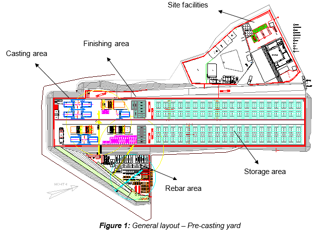
Ho Chi Minh City Urban Railway Construction Project – Ben Thanh – Suoi Tien section (Line 1), Contract Package 2 connsists of approximately 12 km long of elevated viaduct structures, erected by span-by-span Method.
1.3 SCOPE OF WORK
This procedure is established for the Geometry Control of the segments produced using short line casting method at the Precasting Yard and shall include the following items:
- The purpose of Reference & Survey towers in the Precasting Yard.
- All measuring equipment, procedures and the location of survey plates on each segment.
- A Geometry Control procedure for the vertical and horizontal alignment control for the precasting of segment, including survey controls and procedures, observations, checks, computational and/or graphical methods and correction measures.
1.4 REFERENCES
- Specifications:
- Reference is made to clause 12.4.1 “Precast segment casting” (4) “Casting control geometry” of Outline Construction Specification Package 2: Civil (Elevated & Depot).
All reference documents are intended to refer to the last issued revision.
1.5 DEFINITIONS
In this Terms & conditions the meanings assigned to words and expressions shall be the following:
“Match-Casting (M/C)” means the technique of casting a new segment between a fixed bulkhead on one end and its adjacent segment (M/C segment) on the other end.
“Geometry Control” means the reference to the segmentation, adjustment computations and production of as-cast coordinates and levels to enable the precast spans to conform to the design alignment and profile once erected.
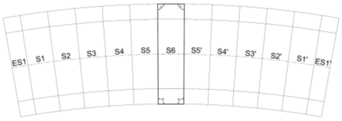
“Segmentation” means the process of breaking the viaduct spans into individual segments, and pre-calculating the theoretical positions of every segment joint, in relation to the alignment and profile of the project as supplied by the main contractor.
“Survey plates” means the positioned in the bottom of segment to enable survey readings to be recorded to points with known theoretical position before the forms are stripped.
“Local coordinates” means the information required to cast the segments in their correct spatial relationship, so that when erected the span will conform to the theoretical alignment of the bridge. It is computed from the supplied alignment geometry for each span.
“Global coordinates” means the information required to erect the segments in their correct spatial position, relevant to the theoretical alignment of the bridge. It is computed from the readings taken after casting of all of the segments in a span and is in the form of horizontal coordinates and levels of the survey inserts placed in the segment during casting.
“Geometrical Control Program (GCP)” means the software for controlling segment geometry during casting, both for adjustment of the match Cast segment and for computing the geometry of the segments.
“Formwork adjustment” means the preparation of formwork for casting a segment, based on the as-cast survey of the segment previously cast.
“Survey tower” means the reinforced concrete columns aligned perpendicular to the fixed bulkhead of each precasting bed, which supports survey equipment to allow formwork adjustment and as-cast segments survey.
“Survey reference point” means the reference point placed in a Precasting Yard to be used as reference target will never move in time to calibrate the Survey tower position.
“Match Cast Segment” means the previously cast segment to be adjusted and forms the stop end at the opposite end of the mould to the fixed bulkhead.
“Wet Cast Segment” means the segment being cast and is between the fixed bulkhead and the match cast segment.
Further definitions have been given in Section 1.5 “Definitions” of the method Statement “General Pre-casting Works at Pre-casting Yard” UMRTL1-CP2-CSYD-CWS-MST-00012.
2. SAFETY & ENVIRONMENTAL RISKS
2.1 HAZARD ANALYSIS & RISK ASSESSMENT
Hazards Analysis and Risks assessment are carried out and attached in the present method Statement. This document will identify all the hazards to ensure adequate control measures and strategies are in place to mitigate as much as possible the risks (Refer to appendix A).
All personnel carrying out the work will be properly trained by experienced supervision. Besides, all personnel shall wear the appropriate PPE (Personal Protective Equipment), such as safety shoes, safety helmet, safety gloves and safety harness if required.
2.2 TOOLS AND EQUIPMENT
All the electronic precision apparatus for survey readings and segment settings shall be calibrated and fit for its purpose in precasting operations, and covered to protect from the sun or the rain. Surveyors must ensure that they are in good condition to use.
Were applicable, official documents and calibration certificates are to be produced.
2.3 ACCIDENT / INCIDENT
In the event of an accident/incident, response will be as per the Health and Safety Plan. Prestart and toolbox talk will reinforce safety requirements prior to commencement of the works.
3. CONSTRUCTION RESOURCES
In principle every type of work involves the following resources:
3.1 PERSONNEL
- Survey Manager
- Surveyors
- Assistant surveyor
- Supervisor
- Workers
3.2 PLANT, EQUIPMENT & TOOLS
- Surveying instruments (Total stations and auto-levels)
- Survey staves
- Prism and prism pole
- Steadying struts for staff and prism pole
- Measuring tapes, marking pens, pencils
- Chalk line and ink line
- Short Line moulds
- Survey platforms
- Survey plates
Note: This list only provides a preliminary overview of resources which can be possibly used during segment precasting operations, so that it does not necessarily prevent personnel to use other equipment plants and tools.
4. CONSTRUCTION PROCESS
4.1 GENERAL
Geometry control is required to ensure that the segments are fabricated in accordance with the designed alignment and profile of the viaduct and the relevant shop drawings issued for construction following the 3 axis directions (X;Y;Z).
To ensure that the segments fit together when erected in their final position, the concept of “match casting” is employed. Match casting is the technique of casting a new segment between a fixed bulkhead on one end and its adjacent segment on the other end.
The first segment to be cast is flat with only the segment side lengths being required.
After casting, this first segment is moved to the match cast position to be the stop end for the next segment to be cast. When the new segment is cast, the exact imprint of the match cast segment is cast into the new segment, thereby providing a matched interface when the segments are reunited in the final structure.
In the case of the segments for this project, the spans to be erected by the span-by-span method are cast straight from pier to pier with no vertical curvature. Horizontal curvature is introduced into a span by making one side of the segments shorter than the other, with curved spans being defined in this project as minimum radius of 300 meters.
The key to controlling the geometry of a segmental bridge is managing the geometric relationship of one segment to the segments adjacent to it. In essence the global coordinates of each segments control paints or survey plates are translated and rotated into a local system based on the casting bed.
The positions of the 4 survey plates placed at bottom slab is as shown:
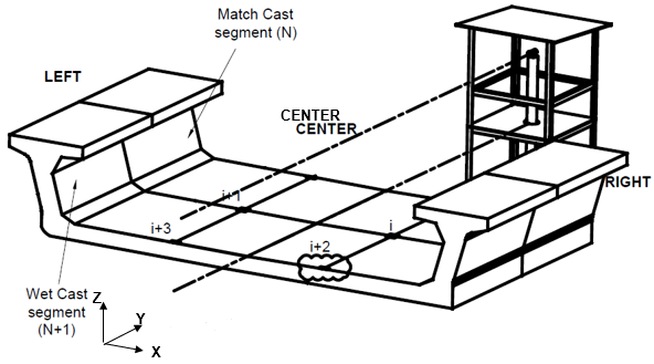
The goal of the geometry software is to monitor the casting operations and establish cast curves segment by segment to verify that the actual geometry of the span is closely following the designed profile and alignment. After each segment is cast, the geometry of the survey plates is compared to the theoretical geometry, and the corrections to be applied to the match cast segment for the next pour to correct for the inevitable small distortions that occur during casting. Each survey plate is used to control the horizontal, vertical and rotational alignment. The geometry is solely dictated by the position of the match cast segment relative to the wet cast segment, and the wet cast segment is always poured against the fixed bulkhead.
The need for good control of span length is due to the requirement for a 100mm gap between PS.
Extreme care is required in segment marking and identification, and mould numbers and markings on match cast segments and direction of casting shall be confirmed and checked by a second person at the time of each survey.
The span casting programme supplied by the Precasting Yard Manager shall be followed and recorded of the time and date of casting for each segment shall be made. Staff allocations and a roster shall be established to ensure that survey is available when needed at each mould. The survey is a critical part of the process, as concrete pouring and stripping cannot commence until survey is satisfied that the mould are correctly adjusted and the cast segment readings have been verified as correct.
4.2 SEGMENTATION AND DATA PREPARATION
The following information shall be compiled from SCC:
- Rail alignment information
- Segment layout and nominal segment length
- Setting out arrangement at pier
- Bearing plinth sizes
- Precamber (if any)
Based on these information, the centreline geometry of the bridge deck shall be established. This include the true segment length, Easting, Northing, level, bearing along segment axis and crossfall.
Having this information also allows the setting out coordinates, levels and dimensions of the bearing downstand. Adjustment of the bearing downstand bottom forms is only required when the gradient of the span exceeds 0.4%. This is achieved by measuring down to the adjustable plate from a straightedge placed across the bottom form.
The segmentation shall be carried out in accordance with approved shop drawings and utilizing the Main Contractor coordinates and levels. All data received shall be checked to confirm that the correct data has been received for each span and that the segment levels correctly relate to the track levels. Coordinates shall be overlayed on Autocad drawing, to confirm the correct alignment.
The casting curve of each span needs to be calculated from the following data:
- Geometric/Mathematical definitions of precast segment centrelines for all spans
- Setting out coordinates, chainages and azimuths of all pier locations
- Precamber values of spans at each segment joint, if any.
- Number of segment required in each span
- Segment numbering system to be used
The horizontal, vertical and rotational offsets of each segment joints in each span are computed relative to the first segment cast in that span. The offsets define the casting curve, such that when the segments are erected they will achieve the desired alignment, and it is these offsets that the casting mould is set to for construction of each segment.
The segment joint coordinates shall be calculated from the casting lengths of the spans. The span lengths shown on the Main Contractor’s drawings have been calculated from pier centre coordinates and as such are horizontal distances after erection. The length required for casting is the length on the gradient along the span.
Moreover, in order to maintain the gaps between the pier segments of adjacent spans, account should be taken of time dependent changes in the segments between casting and erection. The span length at casting is required to be slightly longer to accommodate elastic shortening after PT and concrete shrinkage.
After erection and tendon stressing, the span will become shorter due to elastic shortening and long term effects. The amount of shortening is dependent of span length, the total PT force after lock off, the average cross section area of the match cast face and the modulus of elasticity of the concrete.
The difference in span length due to elastic shortening, concrete shrinkage thermal effects and any other effects to be taken into account shall be supplied by SCC for each span.
Currently, it has been estimated that the amount of shortening will be compensated by epoxy applied at each segment joint.
4.3 GEOMETRICAL CONTROL PROGRAM (GCP)
The geometry control program used is proprietary of FVR JV supplier. The Programmed worksheet (in XLS file) – “Read Only” version is issued to FVR for the application of the Geometry Control methodology to segmental casting operations following short line casting method. This geometry control system uses the measurements and relative levels between 4 defined points in a segment and their geometrical relationship with the defined points in the adjacent segment in order to compute the measurement and levels required in order to setup the latter segment that will act as the counter mould formwork for the next segment to be cast.
FVR staff and surveyor shall input the measurement data and the level recorded during survey works and the program will “self-calculate/generate” the measurement and level for setting up the next segment having taken into consideration that the as-built measurement and level of previous segment. The as-built measurement of the previous segment may have some deviations due to mould vibrations etc.
4.3.1 GCP INPUTS DATA
Two different surveyors are to take the levels and measurements of the 4 survey points of each segment independently. The length measurements are to agree within 1mm and the level measurements are to agree within 1mm. Any measurements not reaching this tolerance shall be retaken. The average of these two measurements are to be used as the data input for the GCP.
4.3.2 GCP OUTPUTS DATA
The outputs of the GCP is the as-constructed coordinates of the 4 control points in each segment. The program then automatically transformed the coordinates to the global coordinate system to be used by surveyor for segment erection works.
4.3.3 CORRECTION METHOD
The dimensions that define the shape of a segment to be cast are given by the GCP for each casting run (based on as-built survey of the matchcast segment). These are lengths from the bulkhead face to matchcast segment joint and levels of the matchcast segment. These set out dimensions are entered into a survey book used by the surveyors when setting out the segment to be cast.
4.3.4 GCP – GRAPHICAL MONITORING OF CASTING PROGRESS
The calculation spreadsheet includes 3 charts that can be used to visually monitor the progress of the casting against the desired casting shape, so it is possible to easily check the vertical, horizontal and rotational deviations that occur during the casting process. An example of the 3 charts from a real project are attached in Appendix F.
4.3.5 MANUAL FOR GEOMETRY CONTROL SYSTEM
Refer to Appendix G
4.4 SURVEY FOR SHORT LINE GEOMETRY CONTROL
4.4.1 SHORT LINE TYPICAL MOULD
Local coordinate for curved span moulds shall be prepared by the software package from the segmentation data. This data in the form of coordinates and heights of the survey plates is stored as a database in the GCP software. A simplified extract giving the left and right segment lengths at the outside of the webs shall be prepared for the use of the reinforcement cage fabricators and the mould operators.
In the wet segment, 2 survey plates are fixed using a holding plates firmly bolted to the fixed bulkhead while 2 other survey plates are bolted butt together to the embedded survey plate of the match-cast segment. Segment length of wet segment is measurement between these firmly positioned survey plates; from bulkhead to match-cast side. The setting out information also contains diagonal measurements between the survey plates which are used for setting the lateral position of the match cast segment.
The first segment of a span to be cast has 2 survey plates firmly bolted to bulkhead and 2 other survey plates bolted to the moveable bulkhead. The segment is cast flat with bottom soffit level.
For subsequent segments, the match cast segment shall be adjusted to achieve the required geometry for the wet cast segment. Measurements shall be taken to an accuracy of +/-0.25mm. However, the difficulties of adjusting perfectly the match-cast segment are recognised and any minor deviation shall be recorded accordingly as the software can accommodate these setting up errors and can correct on the next segment to be cast. The software will identify and ask for re-survey (measurement and level) if the deviation is outside the tolerable dimension. The diagonals (which control the transverse position of the match cast segment) shall be checked after the left and right segment lengths have been set.
The mould operators shall have levelled the bottom form using a spirit level and the screw jacks shall be free before adjusting the levels on the match cast segment. The bottom form of the wet cast segment shall be lowered sufficiently to allow the match cast segment to be moved and positioned freely. After the wet cast segment bottom form has been raised to contact the soffit of the match cast segment, final level readings of the survey plates should be checked, and the segment lengths for the wet cast segment confirmed.
Survey plates are placed at the bottom slab at predetermined locations, using templates before concreting. Before the mould is opened, the levels of all survey plates of wet cast segment shall be taken to ±0.05mm using the centre of the fixed bulkhead as the level reference. Distances between survey plates (including diagonals) shall be measured using graduated measurement tape. Readings shall be taken using precise level (level with attached on micrometer).
4.4.2 SHORT LINE PIER MOULD
Local coordinate for the pier segments of longline spans shall be prepared using an Excel spreadsheet with the cast segment data of the first and last segments cast in the long line bed. The information required includes the left and right segment lengths at the survey plate locations, and the difference in level required between the respective survey plates on each side of the match cast segment. The segment length required shall be measured between the firmly hold survey plates at bulkhead and match-cast face. The required lengths are adjusted to allow for correction of accumulated small casting errors during longline casting and also any changes due to rotation of the fixed bulkhead. Since only the pier segment is being cast and the bottom form of the wet cast has already been set a horizontal plane, the only adjustments required are at the end of the match cast segment away from the fixed bulkhead.
The pier segment bearing downstand inclinations shall be adjusted using a straightedge across the bottom form and measuring down to the movable plate.
Note: Adjustment of match cast segment
The segment length control for short line segment precasting shall be performed by using a graduated steel tape to check that the cast segment lengths and alignment are maintained within tolerances, both individual and cumulative. The segment lengths and alignment of subsequent segments shall be adjusted to maintain the cumulative span length and alignment within the required tolerances.
The match cast segment shall be positioned longitudinally by using a steel measuring tape. After the match cast segment is adjusted, the final measurements shall be confirmed for segment length by measuring both side distances and checking transverse position by checking the diagonal measurements.
Adjustment of fixed bulkhead (if required)
The front bulkhead shall be checked for verticality using a long spirit level.
4.5 INSTRUMENT CALIBRATION & CHECKING
Survey equipment and accessories shall be inspected, and adjusted if necessary, before starting and during work, to ensure that they are operating within the tolerances specified by the manufacturer. Instruments shall have calibration label affixed, giving the due date of the next calibration.
If it is suspected that instruments or ancillary equipment have been damaged, is out of adjustment or is malfunctioning, it shall be withdrawn from service until it has been repaired and/or adjusted, and once found to be in calibration shall have a new calibration label affixed. Any unserviceable equipment shall be clearly marked “Not to be used” (or equivalent marking), and stored away from the equipment in use.
5. ACTIVITY HOLD POINTS
Hold points will be identified in the Inspection & test Plan. Refer to the ITP “Fabrication of Precast Segment” UMRTL1-CP2-CSYD-CWS-PLN-00088
6. INSPECTION AND RECORDS
Survey records shall be actual readings and notes taken in the field during construction and shall be recorded as references in the ITP. Field notes shall be kept in books or on preprinted sheets and shall be in ball point pen, and any alterations shall be struck through and initialled by the surveyor actually taking the readings. The date of the survey, as well as the number of the segment to be cast and the match cat segment, shall always be recorded along with the actual readings. Any major disagreement between two sets of readings, or any difficulties experienced in the course of the survey shall be resolved on site, or if necessary referred to the Survey Manager.