Method Statement of Precast Segment Production Long Line Typical Mould
1. INTRODUCTION
1.1 PURPOSE OF THE DOCUMENT
The purpose of this procedure is to define the sequence of operations to be carried out for the mould preparation & operation works of the Long Line Typical mould, including general arrangements, construction methodologies, technical solutions and other works, and ensures that all works will be conducted safely in accordance with the drawings and the project specifications.
1.2 PROJECT DESCRIPTION
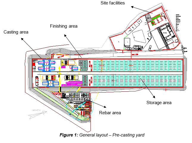
Ho Chi Minh City Urban Railway Construction Project – Ben Thanh – Suoi Tien section (Line 1), contract Package 2 consists of approximately 12 km long of elevated viaduct structures, erected by span-by-span Method.
1.3 SCOPE OF WORK
The purpose of this document is to clarify, step by step, the procedure for the mould preparations & operations, described in the casting sequence for Long Line Typical segments.
1.4 REFERENCES
All reference documents are intended to refer to the last issued revision.
Specifications
- Clause 12.4 “Execution” Section 12-3 of 19 from Outline construction specification – Package 2: Civil (Elevated & Depot)
- “Standard specifications for concrete structures – 2007, Materials and construction” from Japan Society of Civil Engineers, regarding concrete strength achieving minimum 14 MPa prior to mould removal.
Method Statement
- HCMC-261-CSYD-CWS-MST-00012 “General precasting works at precasting yard”
- HCMC-261-CSYD-CWS-MST-00019 “Casting sequence for Long Line Typical segments”
- HCMC-261-CSYD-CWS-MST-00020 “Segment concreting works”
- HCMC-261-CSYD-CWS-MST-00021 “Segment curing”
- HCMC-261-CSYD-CWS-MST-00022 “Segment marking”
- HCMC-261-CSYD-CWS-MST-00023 “Segment lifting & handling works”
- HCMC-261-CSYD-CWS-MST-00040 “Precast segment production – Short Line Pier mould”
- HCMC-261-CSYD-CWS-MST-00042 “Geometry Control for Long Line Casting Method”
Approval of materials
- “Mould release Agent”
1.5 DEFINITIONS
All relevant definitions have been given in Section 1.5 “Definitions” of the Method Statement “General precasting works at precasting yard” HCMC-261-CSYD-CWS-MST-00012
- Lifting frame for segment
Also called “Spreader beam”, the lifting frame that is required for the lifting and shifting of the complete segment from the mould either to the finishing area or storage area. The lifting frame shall be designed so that there is no permanent distortion of the segment either during lifting, shifting or placing on trailer prior to deliver on site.
- Lifting frame for rebar cage
Lifting frame that is required for the lifting and shifting of the fabricated rebar cage from the rebar jig area to the mould. The lifting frame shall be designed so that there is no permanent distortion of the rebar cage either during lifting, transport or placing.
- Mould release agent
Chemical product which provide quick, clean and easy stripping of moulds and formwork, and ensure high quality stain-free concrete.
- Debonding agent
Product which is applied on the match-cast segment face prior to cast the new segment.
2. SAFETY & ENVIRONMENTAL RISKS
2.1 HAZARD ANALYSIS & RISK ASSESSMENT
Hazards Analysis and Risks assessment are carried out and attached in each method statement. This document will identify all the hazards to ensure adequate control measures and strategies are in place to mitigate as much as possible the risks (Appendix A).
All personnel carrying out the work will be properly trained by experienced supervision. Besides, all personnel shall wear the appropriate PPE (Personal Protective Equipment), such as Safety shoes, safety helmet and safety harness if required.
2.2 TOOLS AND EQUIPMENT
All tools & equipment shall be in safe condition before utilisation and fit for its purpose.
2.3 EMERGENCY RESPONSE
In the event of an accident/incident, response will carried out in the appropriate procedure, such as:
- Remedial Actions, proposing actions to ensure that the Accident/Incident will be fully fixed, as required, managed by the Responsible within a target date.
- Preventive Actions, proposing actions to ensure that the Accident/Incident will never happen again, including for example: Toolbox Meeting (TBM) held by the Safety Officer to ensure that Site Team (Workers, Supervisors & Engineers) fully understand methods & risks.
Prestart and Toolbox talk will reinforce safety requirements prior to commencement of the work.
3. CONSTRUCTION RESOURCES
In principle every type of work involves the following resources:
3.1 PERSONNEL
The personnel involved are such as:
- Precasting yard Manager
- Segment casting Superintendent
- Site engineers
- Quality engineers
- Safety officers
- Supervisors
- Plant Operators (Tower cranes & Gantry Cranes)
- Riggers
- Workers
3.2 PLANT AND TOOLS
The following equipment shall be used for all precasting works:
- Long Line Typical (LLT) mould
- Gantry cranes 50 & 10T
- Tower crane TC#1 (6.89ton – 50m)
- Lifting frame for segment (also called “spreader beam”)
- Lifting frame for rebar cage
- Lifting frame for Stop-End
- Electrical tools
- Chains / slings / shackles
- Chain blocks
- Generator set
- Air compressor & compressed air network
Note that this list only provides a preliminary overview of resources which can be possibly used and does not necessarily prevent personnel to use other equipment plants and tools.
3.3 MATERIALS
Concrete (Provided by Sumitomo Corporation)
Rebar cage (equipped with corrugated PT duct and spacer blocks)
Mould release agent
Debonding agent
Corrugated PT ducts
Inserts
4. CONSTRUCTION SEQUENCE
4.1 INTRODUCTION
In the precasting yard, all 4,587 segments shall be manufactured by match-cast principle. In match-casting, the previously Fresh-Cast (F/C) segment, after being cast, is defined as counter mould (Match-Cast M/C) segment; the new segment will be cast against, ensuring a perfect unique connection match cast face.
Nearly 60% of these segments are of straight spans. Typical segment of straight spans will be cast using long line mould. The pier segments of the straight span are still cast at short line pier mould using match-cast typical segment. The match-cast typical segment cast at the long line mould is transferred to the short line pier mould either directly from the long line mould or from storage area using the 50ton gantry crane.
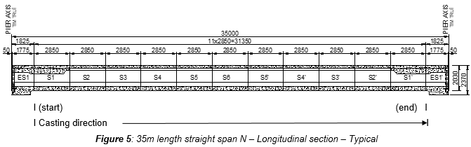
The long line mould differs from short line mould such that the soffit is fixed for the total length of all typical segments within the span. The fixed soffit is called casting bed. There are 2 type of casting bed – 1st type is 33.76m long for casting typical segment at maximum span length of 37m and 2nd type is 31.76m long for casting typical segments at maximum span length of 35m.
There are 3 casting beds; 2 sets of mould on each casting bed and therefore total 6 sets of mould.
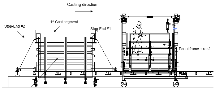
The 1st typical segment is cast at the long line mould using 2 steel stop-ends.
After the concrete has been poured, and the stripping concrete strength required reached, the elements of the mould shall be stripped and shifted to the next adjacent position. The element of the mould is shifted either by gantry crane or pushed on guided rollers on rails.
The 1st cast segment is used as the match-cast segment and is maintained on the fixed soffit for the required curing time (typically 3 days age). The 2nd segment is cast against the 1st segment with the other side formed using the steel stop-end.
Casting of remaining typical segments shall be similar to the production of the 2nd segment using the previous cast segment as match-cast unit.
Each typical segment shall be produced in accordance with all the relevant issued for construction shop drawings and the geometry control sheets.
4.2 DESCRIPTION
Listing of 3 long line casting beds and 6 moulds for the production of straight span typical segments:
| Mould # | Casting Bed | Mould | Remarks |
|---|---|---|---|
| 1 | Long line casting bed #1-LLT#1 | Mould LLT#1-A | For maximum 37m span |
| 2 | Mould LLT#1-B | For maximum 37m span | |
| 3 | Long line casting bed #2-LLT#2 | Mould LLT#2-A | For maximum 35m span |
| 4 | Mould LLT#2-B | For maximum 35m span | |
| 5 | Long line casting bed #3-LLT#3 | Mould LLT#3-A | For maximum 35m span |
| 6 | Mould LLT#3-B | For maximum 35m span |
4.3 COMPONENTS
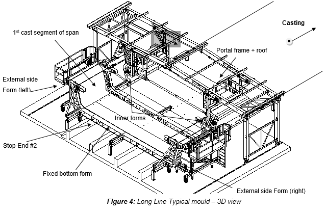
The mould consists of different movable elements that can be joined together to compose the form of the segment. Each casting bed has 2 sets of moulds. Each set of mould has:
| 1. External side forms (left & right) | 1 Set |
| 2. Inner forms (left & right) | 1 Set |
| 3. Portal frame for inner form (including the roof) | 1 Set |
| 4. Stop-End #1 (common stop-end) | 1 No |
| 5. Stop-End #2 (Stop-End used to cast the 1st segment) | 3 Nos shared for 9 formwork |
| 6. Hydraulic system (for inner forms) | 1 Set |
Note that all these quantities have to be multiple by 2, due to each Long Line mould is able to cast two segments simultaneously.
4.4 GENERAL ARRANGEMENT OF CASTING
For 35m straight span length, the first segment is the segment “S1”.
The pier segment of the straight span is cast at short line pier mould against match-cast typical segment. The match-cast typical segment cast at the long line mould is transferred to the short line pier mould either directly from the long line mould or from storage area using the 50ton gantry crane.
4.5 MOULD OPERATION CYCLE FOR 1ST SEGMENT- TYPE S1
- Clean stop end #1, using lifting beam lift stop end #1 to location at soffit end and install
- Once installation of stop end #1 complete, release lifting beam
- Mark the position of stop-end #2.
- Clean external form, position and pre-close in contact with soffit
- Apply mould release agent to stop-end #1 and external form. Apply release agent to soffit last.
- In parallel, clean inner forms and apply the mould release agent.
- In parallel, clean stop end #2 and apply mould release agent.
- Rebar cage is store next to the casting location, completed and equipped with corrugated PT duct and spacer blocks. Place the pre-checked rebar cage in the mould.
- Place and position the stop-end #2.
- Install “satujo” inside all PT ducts
- Install any inserts at web and edge bottom slab (which is not accessible once inner core is closed)
- The inspection prior to inner form push and mould closure.
- Shift on rail the portal frame (with inner forms) to casting position.
- Final closing of inner forms & external side forms against both stop-end #1 and stop end #2
- Tie rod tightening between external and inner forms and horizontal pipe props installed between inner form sides
- Install all inserts at top flange and bottom slab (exposed section)
- Final survey check- checking dimension and levels
*Refer to the method statement “Geometry control for long line casting method” HCMC-261-CSYD-CWS-MST-00042*
- Inflate completely “satujo” (just before concreting)
- Final inspection before casting
- Cast long line typical segment S1 & concrete finishing (floating)
Refer to the method statement “Segment concreting works” HCMC-261-CSYD-CWS-MST-00020
- Cure segment
Refer to the method statement “Curing of segments” HCMC-261-CSYD-CWS-MST-00021
- As-built survey prior to demoulding
Refer to the method statement “Geometry Control for Long Line Casting Method” HCMC-261-CSYD-CWS-MST-00042
- Check early concrete strength of minimum 14 Mpa prior to removal of forms
- Segment is left on soffit until concrete strength of minimum 25 MPa and typically 3 days prior to lifting from casting bed
4.6 MOULD OPERATION CYCLE FOR 2ND & SUBSEQUENT SEGMENTS
- Once concrete hardened (typically 3 or 4 hours after completion of concrete pouring), remove inflatable tubes (also called “satujo”)
- Survey of as-built geometry of previous cast segment
Refer to the method statement “Geometry Control for Long Line Casting Method” HCMC-261-CSYD-CWS-MST-00042
- After required early concrete strength of minimum 14 Mpa is achieved, strip inner forms
- Shift on rail portal frame (with inner forms) behind the stop-end.
- In parallel, marking of segment (ID number, No. span, date of casting & arrow)
Refer to the method statement “Segment marking” HCMC-261-CSYD-CWS-MST-00022
- Strip and shift external side forms.
- In parallel, clean inner forms and apply the mould release agent.
- To cast segment S2, remove both stop-ends #1 and stop-end #2 from segment S1. For subsequent segments, remove the single stop-end.
- Cast segment is used as match-cast segment (M/C).
- Mark position of stop end.
- Apply the debonding agent to M/C face (segment section area with shear keys)
- Clean external sides forms and apply the mould release agent.
- Position & pre-close the external side forms.
- Clean soffit and apply the mould release agent.
- Rebar cage is store next to the casting location, completed and equiped with corrugated PT duct and spacer blocks. Place the pre-checked rebar cage in the mould.
- Place and position the stop-end.
- Install “satujo” inside all PT ducts
- Install any inserts at web and edge bottom slab (which is not accessible once inner core is closed)
- SCC inspection prior to formworks closure.
- Shift on rail the portal frame (with inner forms) to casting position.
- Final closing of inner forms & external side forms against stop-end and M/C segment.
- Install all inserts at top flange and bottom slab (exposed section)
- Final survey check- checking dimension and level
Refer to the method statement “Geometry control for long line casting method” HCMC-261-CSYD-CWS-MST-00042
- Inflate completely “satujo”
- Final inspection before casting
- Cast long line typical segment & concrete finishing (floating)
Refer to the method statement “Segment concreting works” HCMC-261-CSYD-CWS-MST-00020
- Cure segment
Refer to the method statement “Curing of segments” HCMC-261-CSYD-CWS-MST-00021
- Segment is left on soffit until concrete strength of minimum 25 Mpa and typically 3 days prior to lifting from casting bed
- Transfer cured segment to finishing area or pier mould. Segment S1 and S1’ are used as match-cast unit for casting pier segments (refer Figure 5).
Refer to the method statement “Segment lifting & handling works” HCMC-261-CSYD-CWS-MST-00023
4.7 MOULD OPERATION CYCLE FOR SEGMENT “S1”
This section will be supplement if request from reader
4.8 MOULD OPERATION CYCLE FOR S2 AND SUBSEQUENT SEGMENTS
The mould cycle elaborated for segment type S2 from page 27 to page 41. The mould cycle for subsequent typical segments is similar to that of S2.
This section will be supplement if request from reader
5. CASTING OF 2 SEPARATE SPANS SEGMENT ON EACH CASTING BED
There are 2 mould in each casting bed and therefore 2 segments are cast concurrently. The sequence of casting the 2 segments can be referred to section 5.4 of “Casting sequence-Long Line Typical Segment” HCMC-261-CSYD-CWS-MST-00019.
6. ACTIVITY HOLD POINTS
Hold points will be identified in the Inspection & test Plan. Refer to the ITP “Precast segment production”
7. INSPECTION & RECORDS
All Inspection / check-lists & documents records will be identified in the Inspection & test Plan. Refer to the ITP “Precast segment production”