Method Statement for Rebar Cage Assembly
1. INTRODUCTION
1.1 PURPOSE OF THE DOCUMENT
The purpose of this procedure is to define the method for rebar cage assembly works, including the installation of corrugated post-tensioning duct, and ensure that all works will be conducted safely in accordance with the drawings and the project specifications.
1.2 PROJECT DESCRIPTION
Ho Chi Minh City Urban Railway Construction Project – Ben Thanh – Suoi Tien section (Line 1), contract Package 2 consists of approximately 12 km long of elevated viaduct structures, erected by span-by-span Method.
1.3 SCOPE OF WORK
This method statement defines the prefabrication of reinforcement cages for precast concrete segments at the precasting yard, composing the viaducts of HCMC Line 1 – Metro Project.
Included:
- Pre-assembling on jigs
- Installation of corrugated PT duct
- Placing of spacer blocks
- Tagging and lifting of rebar cages
- Storage or rebar cage
- Handling of rebar cage into the mould
Excluded:
- Cut & bend works (Refer to the method statement “Rebar cut & bend works” HCMC-261-CSYD-CWS-MST-00013
- Placing of inserts
1.4 REFERENCES
Specifications:
- Reference is made to clause 13 “Steel reinforcement” from Outline Construction Specification Package 2: Civil (Elevated & Depot). Steel reinforcement shall comply with the following or equivalent ASTM standards: JIS G 3112 “Steel bars for concrete reinforcement” and JIS G 3117 “Rerolled steel bars for concrete reinforcement”, Vietnamese Industrial Standards and British Standards (BSI).
- Reference is made to clause 6.7 “Installation” – clause 6.7.3 “Ducts”, section 6.10 of 23 from Outline Construction Specification Package 2: Civil (Elevated & Depot). Ducts shall comply with the following or equivalent standards: Japanese Industrial Standards (JIS), Standard Specifications for Concrete – Japan Society Civil Engineers (JSCE), AASHTO & ASTM Standards, Vietnamese Industrial Standards and British Standards (BSI).
Approval of Material:
- Approval of material “Fiber concrete spacers – 40mm”
- Approval of material “Post Tensioning duct”
Method Statement:
- Method Statement “Rebar Cut & Bend works” – HCMC-261-CSYD-CWS-MST-00013
- Method Statement “PT duct fabrication” – HCMC-261-CSYD-CWS-MST-00028
All reference documents are intended to refer to the lastest issued revision.
1.5 DEFINITIONS
In this Terms & conditions the meanings assigned to words and expressions shall be the following:
- “PCY” means Precasting yard
- “C&B” means Cut and Bend works
- “Rebar” means reinforcement bars.
- “Rebar cage” or “reinforcement cage” means the pre-assembly steel reinforcement designed and assembled to suit with the specific shape of segment.
- “Rebar jig” or “Jig” means the steel cage fabrication frame that is required for the fabrication of geometrically and dimensionally accurate rebar cages. The jig will be, where needed, easily adjustable to suit all segment dimensional changes.
- “Post tensioning duct” means the material forming a conduit to accommodate Post Tensioning (PT) tendon installation.
- “Spacer blocks” means the concrete spacer used to maintain the rebar cage in the correct position in the mould and ensure that required concrete cover is respected.
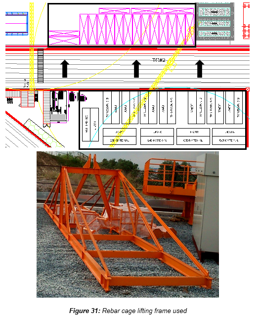
- “Lifting frame for rebar cage” means the frame that is required for the lifting and transporting of the fabricated rebar cage from the rebar jig area to the mould. The lifting frame shall be designed so that there is no permanent distortion of the rebar cage either during lifting, transport or placing.
Further definitions have been given in Section 1.5 “Definitions” of the Method Statement “General precasting works at precasting yard” HCMC-261-CSYD-CWS-MST-00012.
2. SAFETY & ENVIRONMENTAL RISKS
2.1 HAZARD ANALYSIS & RISK ASSESSMENT
Hazards Analysis and Risks assessment are carried out and attached in each Method Statement. This document will identify all the hazards to ensure adequate control measures and strategies are in place to mitigate as much as possible the risks (Appendix A).
All personnel carrying out the work will be properly trained by experienced supervision. Besides, all personnel shall wear the appropriate PPE (Personal Protective Equipment), such as safety shoes, safety helmet and safety harness if required.
2.2 TOOLS AND EQUIPMENT
All tools & equipment shall be in safe condition before utilisation and fit for its purpose.
2.3 EMERGENCY RESPONSE
In the event of an accident/incident, response will be carried out in the appropriate procedure, such as:
- Remedial Actions, proposing actions to ensure that the Accident/Incident will be fully fixed, as required, managed by the responsible within a target date.
- Preventive Actions, proposing actions to ensure that the Accident/Incident will never happen again, including for example: Toolbox Meeting (TBM) held by the Safety Officer to ensure that Site Team (Workers, Supervisors & Engineers) fully understand methods & risks.
3. CONSTRUCTION RESOURCES
3.1 PERSONNEL
The personnel involved are such as: - Site engineers - Supervisors - Operators (tower crane & gantry crane) - Riggers - Steel fixers - Workers
3.2 PLANT AND TOOLS
The following equipment shall be used for the purpose of rebar assembly works: - 10 Ton Gantry Crane (if necessary) - 50 Ton Gantry Crane (if necessary) - Tower cranes TC#1 & 2 (6.89Ton – 50m) - Tower crane TC#3 (4.3Ton – 35m) - Rebar jigs (x13) - Lifting frame for rebar cage - Chains / slings / shackles - Hand tools - Measuring tape, marker
3.3 MATERIALS
- Reinforcement steel rebar (provided by Sumitomo Corporation)
- Steel tie wire
- Concrete spacer block (40mm)
- Corrugated PT duct (manufactured on site)
Refer to the method statement “PT duct fabrication” HCMC-261-CSYD-CWS-MST-00028
4. CONSTRUCTION PROCESS
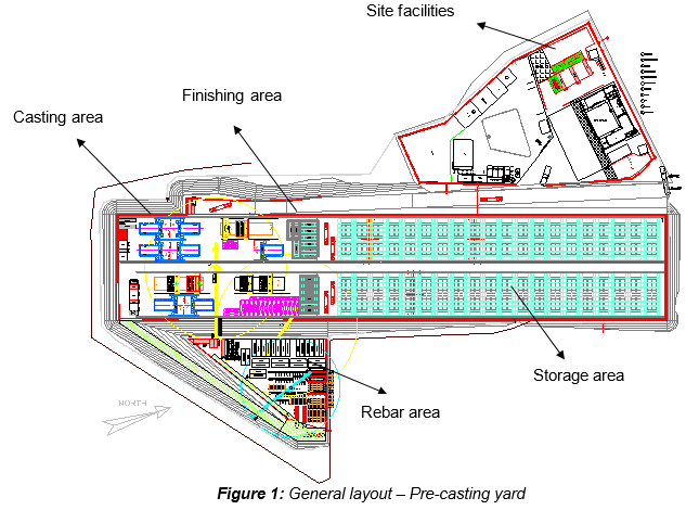
4.1 GENERAL LAYOUT
4.2 PRELIMINARY
Tower crane TC#2 or #3 shall be used to transfer bundled and tagged C&B materials to jig assembly area. Then C&B materials shall be unloaded and stored in clean conditions, beside the jigs, in designated racks per type of bars. Working station must be cleaned daily basis.
The rebar area provide 13 jigs for assembly rebar cages: 4 jigs for pier segment and 9 jigs for typical segment. The use of jigs ensures the quality of bars position and the constancy of overall rebar cage dimensions. Rebar cage assembly for standard segment shall be performed every day, and rebar cage assembly for pier segment shall be performed every 2 days.
The procedure of assembly of rebar cage is as follows:
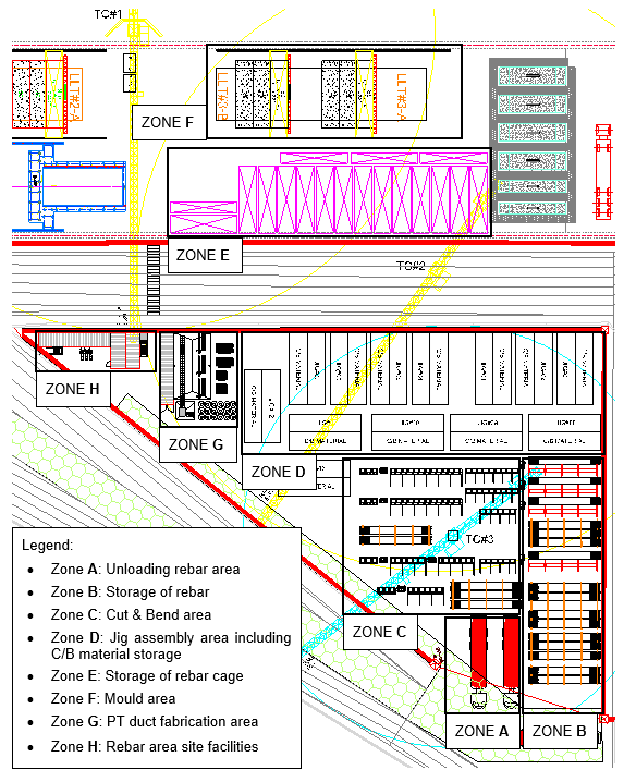
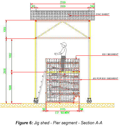
4.3 JIG ASSEMBLY AREA
In the jig assembly area, two types of jigs are used depending on the type of rebar cage to pre-assemble (typical or pier), as shown below:
- JIG SHED FOR TYPICAL SEGMENT – x9
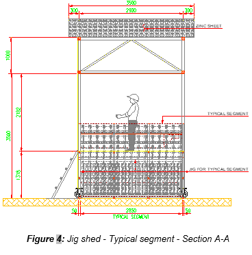
- JIG SHED FOR PIER SEGMENT – x4
4.4 ASSEMBLY OF TYPICAL REBAR CAGE
All reinforcement shall be installed in the rebar jig with general sequence as follow:
- Assembly of bottom slab rebar
- Assembly of web rebar
- Assembly of top flange rebar
4.4.1 STEP 1: MARKING OF JIG
Prior to install rebar, marking of the jig at bottom and web sections shall be carried out by marker. This will help to position each rebar at the exact position as per shop-drawings and also control that all bars are present.
4.4.2 STEP 2: ASSEMBLY OF BOTTOM TRANSVERSAL REBAR MAT (1⁄2)
4.4.3 STEP 3: ASSEMBLY OF BOTTOM TRANSVERSAL REBAR MAT (2.2)
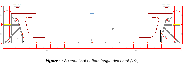
4.4.4 STEP 4: ASSEMBLY OF BOTTOM LONGITUDINAL REBAR MAT (1⁄2)
4.4.5 STEP 5: ASSEMBLY OF ANCHORAGE BOLTS OF OCS POLE
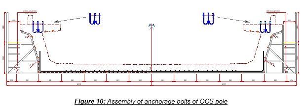
Anchorage bolts shall be fixed within tolerance and vertically by steel template. Refer to Appendix B for details. Holding frame connecting steel template to rebar jig not shown and will be fabricated at site.
4.4.6 STEP 6: ASSEMBLY OF WEB TRANSVERSAL LINKS
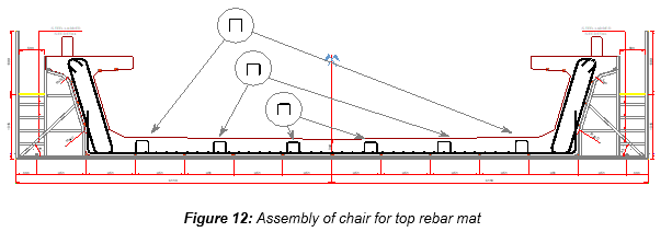
4.4.7 STEP 7: ASSEMBLY OF CHAIRS FOR TOP REBAR MAT
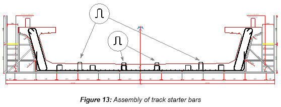
4.4.8 STEP 8: ASSEMBLY OF TRACK STARTER BARS
4.4.9 STEP 9: ASSEMBLY OF BOTTOM SUPPORT BAR FOR PT DUCT INSTALLATION
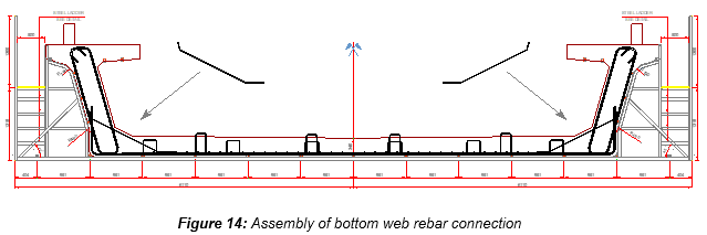
4.4.10 STEP 10: ASSEMBLY OF BOTTOM WEB REBAR LINKS
4.4.11 STEP 11: ASSEMBLY OF TOP TRANSVERSAL REBAR MAT
4.4.12 STEP 12: ASSEMBLY OF WEB TRANSVERSAL PT DUCT SUPPORT
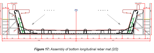
4.4.13 STEP 13: ASSEMBLY OF BOTTOM LONGITUDINAL REBAR MAT (2⁄2)
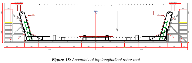
4.4.14 STEP 14: ASSEMBLY OF TOP LONGITUDINAL REBAR MAT
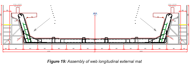
4.4.15 STEP 15: ASSEMBLY OF WEB LONGITUDINAL EXTERNAL MAT
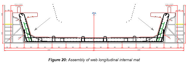
4.4.16 STEP 16: ASSEMBLY OF WEB LONGITUDINAL INTERNAL MAT
4.4.17 STEP 17: ASSEMBLY OF WEB TRANSVERSAL SPACER
4.4.18 STEP 18: ASSEMBLY OF TOP FLANGE TRANSVERSAL REBAR
4.4.19 STEP 19: ASSEMBLY OF TOP FLANGE TRANSVERSAL LINKS
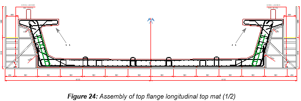
4.4.20 STEP 20: ASSEMBLY OF TOP FLANGE LONGITUDINAL TOP MAT (1⁄2)
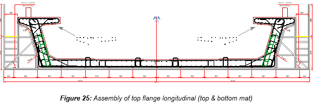
4.4.21 STEP 21: ASSEMBLY OF TOP FLANGE LONGITUDINAL (TOP & BOTTOM MAT)
4.4.22 STEP 22: ASSEMBLY OF TOP FLANGE TRANSVERSAL SPACER
4.4.23 STEP 23: ASSEMBLY OF TOP FLANGE TRANSVERSAL PARAPET
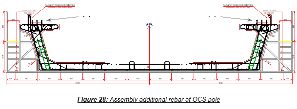
4.4.24 STEP 24: ASSEMBLY OF ADDITIONAL REBAR at OCS pole
4.5 INSTALLATION OF PT DUCT
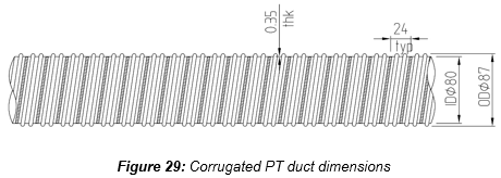
Corrugated PT ducts must be handled carefully to prevent any permanent deformation. It’s important to make sure that the ducts are not subject to any impact to not reduce the diameter during transportation and storage.
The corrugated post tensioning ducts will be accurately aligned and positioned as per shop-drawings.
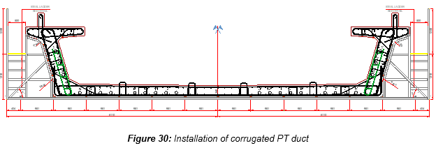
PT ducts shall be held in place by supports, positioned every 600mm as follow:
- Bottom slab: PT duct shall be supported by a single rebar.
- Lateral web: PT duct shall be supported by a steel support, called “ladder”.
It is important to make sure that the duct supports themselves are correctly fixed to the rebar cage. Corrugated PT duct shall be tied by steel tie wire on duct supports to avoid displacement during lifting the rebar cage into the mould.
In order to prevent slush grouting, an inflatable tube called “satujo” shall be installed into ducts before concreting. Refer to the method statement “Precast segment production – Short Line Typical mould” HCMC-261-CSYD-CWS-MST-00015.
4.6 INSTALLATION OF CONCRETE SPACER BLOCKS
Concrete spacer blocks of single size (40mm) will be used to guarantee that the required cover of concrete onto the reinforcement is respected.
Concrete spacers shall be fixed when the rebar cage is still in the jig:
- Segment slab = 2 spacers per m2 shall be installed.
- Underneath the segment web = 4 spacers per m2 shall be installed.
- Internal & external webs = 2 spacers per m2 shall be installed.
- Top flange slab = 2 spacers per m2 shall be installed.
4.7 ADJUSTMENT OF REBAR DUE TO PT DUCT
The checking procedure will be done during shop-drawings process, and if adjustment or rebar is needed, it shall be adjusted in shop-drawings prior to assembling the rebar cage.
4.8 ATTACHING A TAG
Completed rebar cage shall be inspected prior to being removed from jig assembly area, and then if approved, rebar cage shall be tagged with proper identification, showing: - Jig No - Span No - Segment ID - Segment type
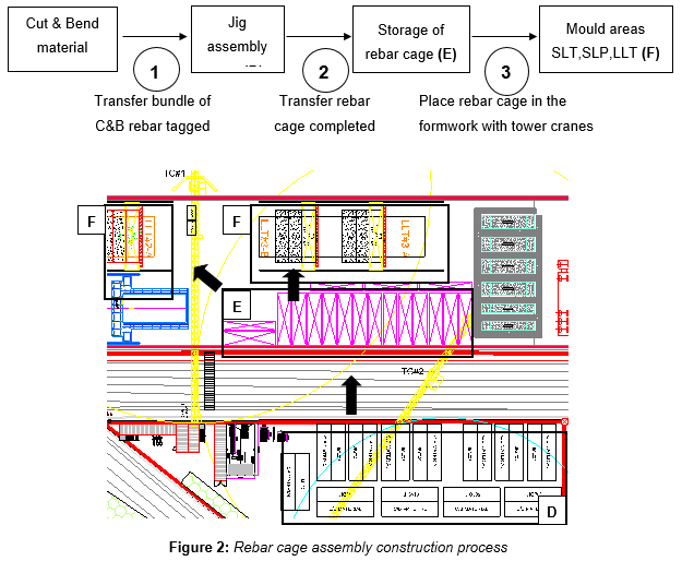
4.9 TRANSFER REBAR CAGE TO STORAGE
Tower crane TC #2 will be used to transfer approved rebar cage to storage area, using a proper designed lifting frame in order to avoid any deformation.
4.10 STORAGE OF REBAR CAGE
Placing the finished rebar cage in temporary storage area on proper timbers support at the soffit and lateral support at web/top flange, if required. Temporary rebar bracing might be added to prevent deformation of the rebar cage.
Any adjustment to the rebar cage including concrete spacers etc… shall be made before closure of inner form in the mould.
4.11 TRANSFER INSIDE FORMWORK MOULD
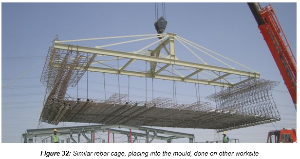
Hooking and lifting of the rebar cage to put in position into the mould shall be done by the same type of lifting frame already previously used, by means of tower crane or gantry crane.
Refer to the method statement “Precast segment production – Short Line Typical mould” HCMC-261-CSYD-CWS-MST-00015
5. ACTIVITY HOLD POINTS
Hold points will be identified in the Inspection & Test Plan. Refer to the ITP “Precast segment production - Reinforcement”
6. INSPECTION & RECORDS
All Inspection / check-lists & documents records will be identified in the Inspection & test Plan. Refer to the ITP “Precast segment production - Reinforcement”
7. ATTACHMENTS
7.1 APPENDIX A: HAZARD ANALYSIS & RISK ASSESSMENT
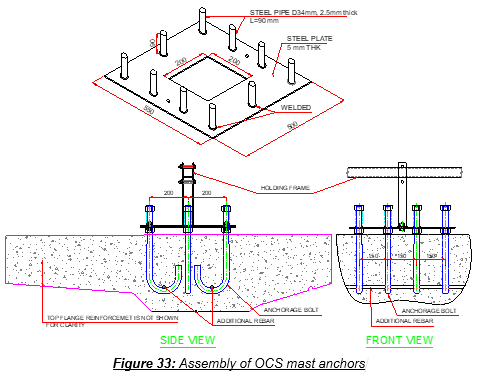
7.2 APPENDIX B: ASSEMBLY OF OCS MAST ANCHORS
- As indicated on drawing CP2-CVS-FT-VDGN-22011 Rev A, concrete parapet to be interrupted at OCS locations. Therefore, no starter bar for concrete parapet in the OCS pole location.
- Latest information of OCS pole anchoring detail is in Appendix C.
- The 27mm diameter anchor bolts shall be supplied by CP3.
- A steel template 5mm thick which incorporates the mast anchor bolts exact positions (10 nos) shall be fabricated. At each location of hole for anchor bolt, a 90mm length of steel pipe-verticality guide (internal diameter = 29mm; top of pipe has 29mm diameter hole) is welded to plate to ensure anchor bolt verticality. Refer to figure below.
- All 10 nos of mast anchor bolts shall be bolted to the steel template with verticality guide pipe. Refer to figure below.
- The steel template with the anchor bolts shall then be placed in the right position within the top flange reinforcement cage; holding frame connect steel template to rebar jig.
- Reinforcement links etc which clash with the mast anchor shall be slightly adjusted leaving a gap approximately 10mm between the mast anchor and the nearest reinforcement.
- The steel template with the anchor shall be left with the rebar cage until the rebar cage is lifted and placed inside the mould.