Method Statement for Rebar Cut & Bend Works
1. INTRODUCTION
1.1 PURPOSE OF THE DOCUMENT
The purpose of this procedure is cut and bend rebar works related to the production of precast segments composing the viaducts of HCMC Line1 – Metro Project.
1.2 PROJECT DESCRIPTION
Ho Chi Minh City Urban Railway Construction Project – Ben Thanh – Suoi Tien section (Line 1), contract Package 2 consists of approximately 12 km long of elevated viaduct structures, erected by span-by-span Method.
1.3 SCOPE OF WORK
This procedure is developed for application in the scope of works and applies to the casting cycle of the Precast Segments.
1.4 REFERENCES
All reference documents are intended to refer to the last issued revision.
- Specifications:
- Reference is made to clause 13.4: “Cutting and Bending Reinforcement” of Outline Construction Specification Package 2: Civil (Elevated & Depot).
- Reinforcement bars shall be cut and bent in accordance with Design Standards for Railway Structures and Commentary (Concrete Structures), (DSRSC-CS), Railway Technical Research Institute, Japan (RTRI-J), British Standard (BS) to the specified shapes and dimensions.
- Document
- MS for General Pre-casting Works at Pre-casting Yard, ref. HCMC-261-CSYD-CWS-MST-00012
1.5 DEFINITIONS
In these Terms & conditions the meanings assigned to words and expressions shall be the following:
- “Rebar jig” means the steel cage fabrication frame that is required for the fabrication of geometrically and dimensionally accurate rebar cages. The jig will be, where needed, easily adjustable to suit all segment dimensional changes.
For further definitions, refer to the Method Statement “General precasting work at precasting yard” HCMC-261-CSYD-CWS-MST-00012
2. SAFETY & ENVIRONMENTAL RISKS
2.1 HAZARD ANALYSIS & RISK ASSESSMENT
Hazards Analysis and Risks assessment are carried out and attached in each Method Statement. This document will identify all the hazards to ensure adequate control measures and strategies are in place to mitigate as much as possible the risks (Appendix A).
All personnel carrying out the work will be properly trained by experienced supervision. Besides, all personnel shall wear the appropriate PPE (Personal Protective Equipment), such as Safety shoes, safety helmet and safety harness if required.
2.2 TOOLS AND EQUIPMENT
All tools & equipment shall be in safe condition before utilisation and fit for its purpose.
2.3 EMERGENCY RESPONSE
In the event of an accident/incident, response will carried out in the appropriate procedure, such as:
- Remedial Actions, proposing actions to ensure that the Accident/Incident will be fully fixed, as required, managed by the Responsible within a target date.
- Preventive Actions, proposing actions to ensure that the Accident/Incident will never happen again, including for example: Toolbox Meeting (TBM) held by the Safety Officer to ensure that Site Team (Workers, Supervisors & Engineers) fully understand methods & risks.
3. CONSTRUCTION RESOURCES
In principle every type of work involves the following resources:
3.1 PERSONNEL
The personnel involved are such as:
- Site engineer
- Supervisors
- Workers
- Tower crane operator
- Riggers
3.2 PLANT AND TOOLS
The following equipment shall be used for purpose of cut & bend works:
- Bar cutting machines
- Bar bending machines
- Measuring tape, chalk
- Tower crane TC #2 (6.89 Ton – 50m)
- Tower crane TC #3 (4.3 Ton – 35m)
- Hand tools
- Chains / slings / shackles
- Safety goggles + work gloves
3.3 MATERIALS
- Reinforcement steel rebar (provided by General Contractor)
4. CONSTRUCTION PROCESS
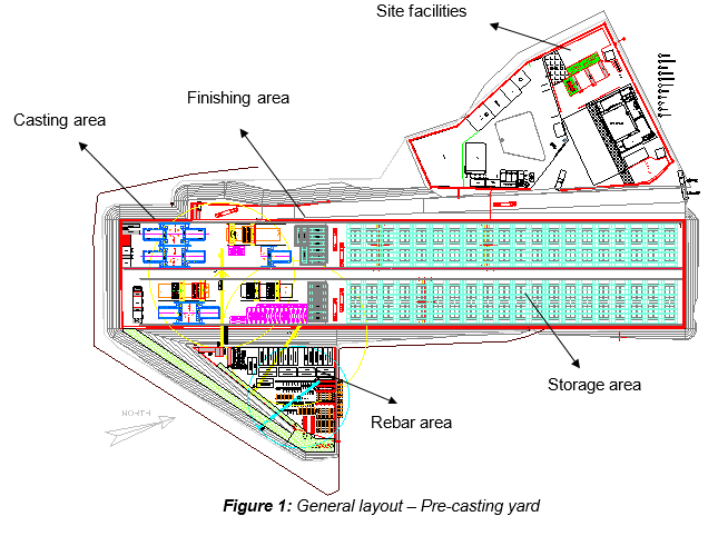
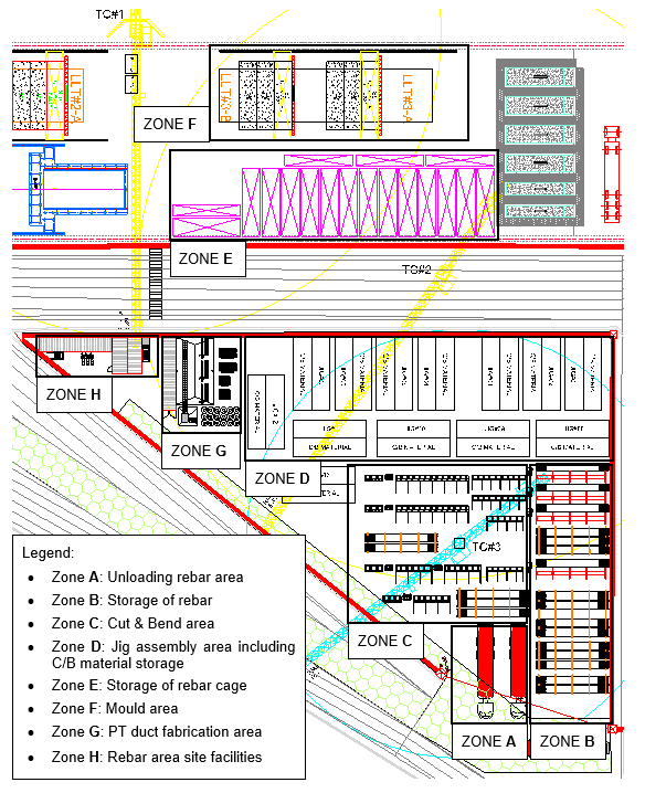
4.1 GENERAL LAYOUT
4.2 DELIVERY OF REBAR
|
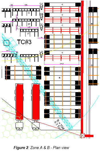
Straigth construction bars will be provided by General Contractor. All the bundles of rebar shall be inspected against the delivery docket. Random checking of the numbers of bar per bundle will also be undertaken. Mills Certificate shall be attached to delivery docket. Bundles of standard rebar size are transported to precast yard by trailers, and are unloaded by tower crane TC#3 to storage. Note: the maximum lifting capacity of tower crane is 4.3 tonnes at tip 35m. The delivered rebar can be either standard or pre-determined cut length. It shall be stored based on diameter and length. The identification and tagging number shall remain until transfer to cutting area. |
4.3 STORAGE OF REBAR
The rebar will be placed on a storage rack to keep rebar away from stain of eminence water and 100x100mm timbers will be used to separate between each layers of bundles. Each raw material storage rack shall be provided for one single diameter of rebar.
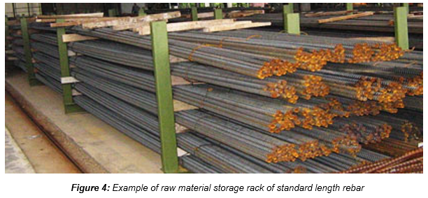
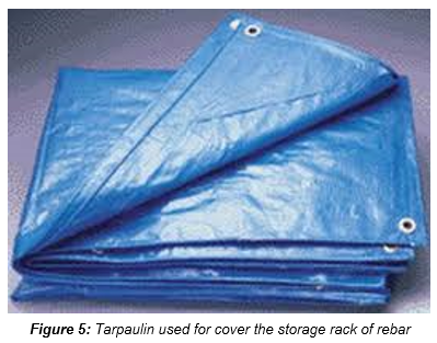
The storage rack is covered with tarpaulin against any rain.
4.4 REBAR CUT & BEND
Rebar cut & bend works shall be performed in 2 shifts (day and night) depending of the activity. The procedure of cut & bend as follow:
4.5 REBAR CUTTING
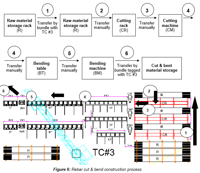
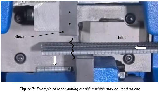
Rebar may be delivered pre-cut to length or standard length as per local regulation. Standard length rebar shall be cut to the required length according to the approved bar bending schedule / cutting sheet. Site engineer shall control and update the list of construction rebar drawing and bar bending schedule approved by the contractor. He shall be fully responsible to issue the copies of approved construction rebar drawing and bar bending schedule to the Supervisor in charge of production, prior to commencement of the cutting and bending of rebar. Rebar from raw material storage rack shall be transferred to raw material storage rack next to cutting machines, by means of bundles using the tower crane TC #3, then transfer manually from these raw material storage rack to the cutting rack, prior to be slide and cut by the cutting machines. The cutting machine operator will setup length and quantity of rebar to be cut. After cutting, rebar will be regrouped per size and diameter using bundles. Each bundle will receive ID tag, and each tag shall receive a traceability number showing diameter cutting length and origin as per straight bar original tags. Then the cut bar is either shifted to the bending machine besides the cut machine (refer to section 4.6 “rebar bending”), or directly to the Cut/Bend Storage material prior to be sent to rebar jig. Both can be either manually or by means of tower crane TC #3.
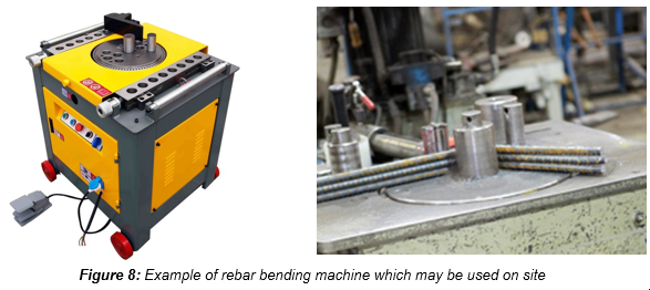
4.6 REBAR BENDING
The rebar shall be bend according to the approved bar bending schedule and shop drawing. The bending works will be carried out using rebar bending machines located within the same area where the cutting machines are located.
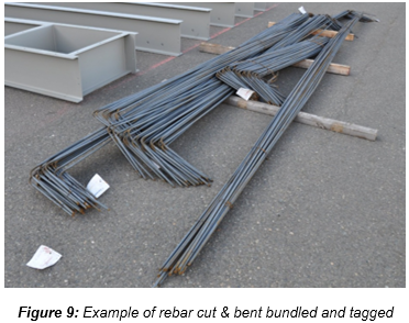
Completed cut & bent rebar shall be inspected in template, and then approved C/B rebar shall be properly bundled and tagged with proper identification prior to be distributed to the rebar jigs by tower crane TC#3.
5. ACTIVITY HOLD POINTS
Hold points will be identified in the Inspection & test Plan. Refer to the ITP “Precast segment production - Reinforcement”
6. INSPECTION & RECORDS
All Inspection / check-lists & documents records will be identified in the Inspection & test Plan. Refer to the ITP “Precast segment production - Reinforcement” QC records shall include:
- Material certificates
- Checksheets
Since reinforcement is supplied by General Contractor, all testing shall be directly done by General Contractor. Testing shall be carried out by the approved third party laboratory (by General Contractor). Mechanical and chemical tests by General Contractor. Specimens testing also shall be by General Contractor